Pages

Friday, 16 October 2020

Document breadboard builds by writing Python code

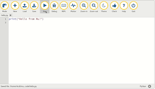
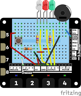
In my last post I mentioned that I was using breadboarder - a Python program that eases the pain of documenting breadboard-based projects.

You write a descriptiopn of your project using a Python-based DSL - a domain-specific language.

It lets you explain what wire or component to add to the breadboard, and where to connect it.

You write code like this:


And it generates markdown and png files which render like this:


It saves hours of layout, you can build complex projects out of simple ones, and everything is under source control.

I need to improve the documentation but breadboarder is on GitHub.


Wednesday, 14 October 2020

Fault-finding breadboarded circuits - a tale from the trenches

blobstar
Yesterday I destroyed an Atmel ATMega328 chip. (That's the chip at the heart of the Arduino.)

The Atmel chips are very well designed, and it's really hard to damage them, but I've managed it twice in the last decade. Yesterday's episode was due to a mistake in wiring up an Arduino clone that I've been building on a breadboard.

The clone is a descendant of Cefn Hoyle's excellent Shrimp design. I decided to build an alternative version which could be programmed using an FTDI cable and made permanent using an Adafruit perma-proto board.

The correct layout (shown above) is easy to follow, but my ageing eyes led me to connect two of the power wires to the wrong pins. When I powered up the board using an FTDI cable the LED didn't blink and I knew something was wrong.

But what?

A simple approach to problem-solving

When something stops working, you focus on what's changed. When you have two versions of something, only one of which works, you focus on the difference.

In my case I had a working version of the design on an Adafruit permo-proto board. When I compared the bread-boarded version with the board that worked I realised the mistake I'd made. I fixed the wiring and tried again.

The bread-boarded version still didn't work.

I rechecked the wiring and convinced myself that there were only minor differences between the bread-boarded and soldered versions. The bread-boarded version uses a crystal and I'd omitted a couple of tiny capacitors that aren't normally necessary, so I added them. Still no joy.

By now the only significant difference between the circuits was the physical chips.

I swapped the chip from the known-good board into the breadboard, powered it up, and...

Success


The board worked!

Here's the perma-proto version blinking as it should.

Clearly, my earlier wiring mistake had fried the ATMega chip.  Once I'd replaced it both versions worked.

I'm documenting the breadboard version for use in an updated version of my e-book Making the Shrimp. I'm using a neat piece of software called breadboarder.

Breadboarder lets you describe a circuit using a simple Python-based DSL (Domain Specific Language). It generates an SVG diagram and step-by-step instructions in plain English.

I'll describe breadboarder in a bit more detail in my next post.


Friday, 9 October 2020

An Adafruit proto Bonnet for the Raspberry Pi, Jetson Nano and Grove I2C


babelboard bonnet
Adafruit's protoBoards lets you make a bread-boarded design permanent, and Seeed Studio's Grove system lets you wire up a prototype really quickly.

In this half-day project I combined the two to create a simple, cheap, flexible prototyping system for the Raspberry Pi and Jetson Nano

The Grove system is based on standard 4-way connectors which can be used to connect digital, analogue and I2C-based components. I've focused on I2C since most of the robots I build use I2C to interact with their environment.

I mentioned the Jetson Nano - a hot topic at the moment, as NVIDIA have just announced a low-cost 2 GB version of the Nano which will be available at the end of the month. One of the clever features of the Nano is that it has a Pi-compatible header, so the bonnet will work on the Nano without modification.

Fritzing the design

I started by laying out an Adafruit bonnet design using Fritzing. The design is really simple. All it does is connect the pins of the Grove connector to the relevant pins on the Pi's GPIO header.

The only minor complication is that the Grove connector has 2mm spaced pins, but past experience has taught me that a little judicious bending allow you to fit one to a 0.1" spaced proto board.

A simple test

I tested the board using a Grove ADC board connected to a Grove potentiometer.

My ADC board is based on the ADC121. I've been a fan of the Grove hardware for a decade, and my board is an old one. It has a default I2C address of 0x55 unlike more recent versions which have a configurable address that defaults to 0x50.

I wrote a short Python script to read the voltage from the potentiometer and ran it. As expected, the voltage changed as I twiddled the knob. Success!

A quick demo

Here's a short video of the output from the zero as I twiddle the knob of the potentiometer.


I can now connect the zero to all kinds of useful I2c devices - servo controllers, motor controllers and a 9-axis motion tracking module.

Coming next

I'm working on an inexpensive LIDAR which reads distance data from eight VL53L1X Time of Flight Sensors using an MCP23008 port expander to selectively enable them. More details soon!

Friday, 25 September 2020

Mu, Edublocks and the Kitronik Inventor's kit

A friend of mine recently asked me about Python programming on the micro:bit. I told him that I wrote a free workbook about that a while back. (If you'd like to get a copy you can sign up here). 

 It's based around the excellent mu editor.

Code with Mu

Mu is a no-frills editor that you can use to develop and run programs on the micro:bit, Adafruit CircuitPython boards, the Raspberry Pi and other Python environments

Mu has just enough features to be usable without being daunting. I love it.

But some young students find text-based programming a bit scary. How can they get started?

Code with Edublocks

Some younger programmers are happier with block-based (visual) programming. For them, Edublocks is a great solution.

Edublocks is block based, runs in your browser, and looks like the popular Scratch environment, but it's Python-oriented.

Here's the Edublocks version of the code for the first experiment for Kitronik's excellent micro:bit Inventor's Kit.

Edublocks allows you to assemble a block-based program in your browser. Then, as with mu, you can deploy it to a

  1. micro:bit, 
  2. Raspberry Pi,
  3. CircuitPython board or 
  4. a Python environment on your laptop or workstation.

The Edublocks interface will look familiar to anyone who has explored block-based programming, but it has a secret power!

Blocks or Python

If you click on the button marked BLOCKS the display switches to show you the Python  script that corresponds to your block-based code.

That helps users to get familiar with normal text-based Python programming. There's so much fascinating and educational Python code on the web, but you need to be happy with text-based programming to master it.

There's more!

To help with moving to text-based code there's a split screen mode that shows both views at once.

Edublocks is s delightful project. Amazingly, Joshua Lowe was 14 when he created it!

Josh was introduced to programming by Alan O'Donohoe (@teknoteacher) and knew immediately that he wanted a career as a programmer. With Edublocks Josh has shared his passion with a new generation of programmers.

If there's enough interest I'll post some more Edublocks examples based on the experiments in the Kitronik Inventor's kit. Let me know in the comments below or in the micro:bit and MicroPython FaceBook group.

Wednesday, 23 September 2020

Build your own Arduino clone - updating the Shrimp

A Shrimp assembled

A while ago I ran a series of workshops showing how to build your own Arduino clone, based on a low-cost e-book called Making the Shrimp.


The book needs an update and I'm looking for reviewers. They will get a free copy of the book and a free kit to build. If you're interested, sign up here.

Friday, 18 September 2020

Getting started with Pimoroni's Tiny 4WD Rover

Kit contents with extras

I just finished my book on the Pimoroni Explorer HAT, and I'm celebrating!

I have treated myself to a Tiny 4WD Rover kit.

It looks a lot of fun, and should be simple to assemble. The product page has a link to a great blog post from Emma Norling which has detailed build instructions. I'll be following that closely.

I have already encountered one  minor gotcha.

You need a few extras over and above the parts in the kit.

Some of them are mentioned on the product page (battery, Pi zero W), but Emma found she needed spacers to mount the Explorer pHAT on the Pi zero W. I have suitable spacers in stock so I think I'll be OK.

I also got a LIPO shim and a USB charger.

Once I've completed the build I'll document it and provide a link on this blog.

A nice bonus if you hurry! 

Pimoroni are currently offering a free Pi Zero WH for customers spending more than £100 (excluding postage). The offer ends soon, but I managed to get my order in on time which got me the brains for the kit!

HAT book update

I mentioned that I'd finshed Explorer HAT tricks. It's got all the planned content, code and images; I'm wating for feedback from my copy editor and a few reviewers, so it may change a bit. Since the book is on Leanpub, readers will get any upgrades free.

The book price (currently $8 + tax) goes up again on Monday, so if you are thinking of getting it, buy it now! There's a 45-day money back guarantee so it's a risk-free purchase.

Friday, 11 September 2020

Explorer HAT tricks is nearly finished!

If you're thinking of experimenting with the Pimoroni Explorer HAT,  Explorer HAT tricks is a great place to start.

It covers over a dozen simple projects, complete with Python code, and you won't need to do any soldering.

If you're an experienced Pi user, you probably feel you don't need it, and that's fine. But if you're just starting out with Physical Computing, or new to the Explorer HAT, it's well worth a look, and there's a free sample available.

The book is now over 80% complete. You get the book from Leanpub, which means that you get updates free whenever the book changes.

The book was written for use with the Pimoroni Explorer HAT Pro but Pimoroni are currently offering a great deal on their Electronics pHAT kit. The kit costs just £19.92 including a Raspberry Pi zero. !

I've ordered one to experiment with. I know a couple of the projects in the book will need to change, but almost all of them will work unmodified.

I'll write up what works and what doesn't, and I'll be adding an appendix telling you how to set the Pi zero up.

One minor warning; the Pi zero kit does require you to solder a header to the Pi.

Another book is on the way

I'm also working on ideas for a follow-on book. More details soon!

A heads-up on Price

If you're hesitating about getting Explorer HAT tricks, now is a great time to get it. I'll be raising the price (currently a low, low 8$) when the book is finished.

Get the book here


Friday, 4 September 2020

Baby talk - Audio analysis on the Pi

I'm working on two projects at present.

I want to finish my book on the Pimoroni Explorer HAT, and I'm getting close. All of the code examples are available on GitHub, many with documentation, and the book itself is now 70% finished. It's still only $5, but the price goes up this weekend.

I've also started another project - one that I expect to take months or years. It's based on some fascinating work by Jürgen Schmidhuber and his team on a technique they call UDRL - Upside-Down Reinforcement Learning.

It looks as if they have cracked a problem that has been bugging me for decades. How can we get an ANN-based Parent Agent to train a Child Agent without hard-wiring in an unrealistic amount of innate behaviour?

If you're interested in their solution (and have a basic background in reinforcement learning) there are two papers on arxiv that explain it:

Training Agents using Upside-Down Reinforcement Learning and

 Reinforcement Learning Upside Down: Don't Predict Rewards -- Just Map Them to Actions.

 The papers use game-based learning tasks but I want to explore the idea of teaching a Child agent to speak by getting it to imitate the parent.

Sound analysis

The first step of my project is to generate inputs for an ANN from the sounds that the Child agent hears. I'm lucky to have a friend who is an expert on Hearing;   his recommended reading led me to some software on GitHub which analyses sound in much the same way as humans do.

The image to the right is the output generated from a short speech sample. It's like the spectrum you'd get from Fourier Analysis, but it's closer to what experts think the human nervous system does.

Friday, 28 August 2020

Explorer HAT book - two more draft chapters


I've drafted a couple more chapters for Explorer HAT tricks.

They need editing but I will publish a new version of the book with the new chapters next week.

If you've bought it you will get the updates free of course.

The video shows one of the projects - a simulation of a Pelican Crossing.

You can find out more about the book here.

Tuesday, 25 August 2020

Explorer HAT update on its way!

keypad
HAT and Keypad
I am about to update my book about Pimoroni's excellent Explorer Hat.

I've finished the code and the Frizing diagrams for all the planned projects. The next step is to write the remaining chapters that describe them, and I hope to publish a couple of those later this week.

The image on the right shows one of the new projects: a 12-key numeric keypad controlled by the Explorer HAT.

The price for the book is still just $5 (+ VAT for EU buyers) but I'll have to raise the price once I've added more content.

 You can buy the book through LeanPub, so you get a 45-day no-hassle money-back guarantee and you'll get future updates to the book at no additional cost!

If you want to make the most of the Pimoroni HAT, don't wait - get the book while the price is still just $5!

Friday, 5 June 2020

Quantum Computing with qiskit on the Raspberry Pi

IBM Quantum Computer
Quantum Computing is fascinating, and you can now explore it with a Raspberry Pi!

IBM have created Qiskit, a very accessible Python-based framework for Quantum Computing. You can install qiskit on Linux, OS X and Windows platforms.

You can even install it directly on the Raspberry Pi, though the installation is a little tricky and takes quite a while.

(Image copyright IBM)

Qiskit supports the IBM Quantum Experience - a collection of tools and tutorials that enable you to learn about Quantum Computing.

You can explore qiskit via the web or install a local copy. You can even submit your own Quantum Circuits to run on IBM's publicly available Quantum Computers.

 If you're looking for interesting STEM topics to explore, Quantum Computing is worth a look.
If you can use a jupyter notebook to run simple Python code you can explore the qiskit examples.

If you have a basic background in linear algebra and complex numbers you can understand the mathematics that underpins Quantum Computing.

qiskit on the Raspberry Pi


I mentioned earlier that qiskit runs on a Raspberry Pi - a good choice if you cannot easily install qiskit on a workstation or laptop computer.

It's not hard, though it takes an hour or more on an 8GB Pi 4. There are a few pitfalls, but I've listed the steps I took on GitHub.

An alternative solution is to run qiskit on the Pi inside a docker container. I've built a publicly available image on DockerHub.

It's big (about 2 GB) but you can pull (download) it in a few minutes over a fast broadband connection. It runs well on a Pi 3B+ or a Pi 4B of any size.

I've also included the Dockerfile used to build the  Docker image in the same repository, but it's not for the faint-hearted. It takes about 4 hours to build on an 8 GB Pi 4!


Sunday, 26 April 2020

Virtual Pi Wars 2020 was outstanding!

This year Pi Wars went virtual, and it was a huge success.

Mike Horne did a superb job as compère, and the Robot videos were wonderful: always informative, often amusing and of very high quality.

Over the next few days we'll have a chance to vote. It's going to be a very difficult choice!

The Teams presented creative and individual solutions, but some common themes emerged. Lots of teams made use of simulations. Some used custom software based around standard libraries; others were based on specialised open source frameworks like VTK.

Most Robots were programmed in Python, but several used Pi controllers with peripheral Arduino nanos or teensies programmed in C.

Some teams used ToF (Time of flight) sensors for distance sensing and SLAM (Simultaneous location mapping and mapping). A growing number of entrants used OpenCV or plan to use it next year.

Many Teams share their software and designs. I'm looking forward to exploring several of the projects on GitHub as I look through the videos over the next day or so.

Over 300 people watched the virtual presentation. They  savoured three hours of excellent virus-free entertainment. Thanks to everyone involved, and special thanks to Mike Horne and Tim Richardson for turning that bright idea all those years ago into a wonderful, enduring institution.

Tuesday, 7 April 2020

The micro:bit is talking to the VL53L0X ToF sensors!

This chip is no more :(
This morning I got my Arduino sensor driver talking to a micro:bit using SPI.

The Arduino Uno runs at 5 volts, and the micro:bit works at 3v3, so I used a level shifter to connect the two.

My first attempt failed disastrously.

The level shifter I used was based on the TI TXB0108.
I managed to connect the 5v power and inputs to the 3v3 side, and I fear the magic smoke has left the chip.

It's a shame, as the board was my first attempt at soldering SMD devices. It's been sitting unused in my bits box for a few years, though, so it's not the end of the world.

Fortunately I had an Adafruit level shifter breakout based on the same IC. It's well laid out with very clear pin markings and I managed to connect it correctly.

The replacement worked perfectly and the micro:bit MicroPython code was very straightforward. I've listed it below, and it's with the other code on GitHub.

from microbit import *
import struct
from time import sleep

SENSORS = 2

def spi_read(sensor):
    pin16.write_digital(0)  # Chip select
    ibuffer = struct.pack('<B', sensor)
    spi.write(ibuffer)
    result = spi.read(1)
    pin16.write_digital(1)  # Chip select off
    return result

spi.init(baudrate=100000)
while True:
    for i in [0, 1]:
        print(i, ord(spi_read(i)))
        sleep(0.1)


The technology is working. The next step is to build a compact version for Anastasia. I'll report on progress.

Monday, 6 April 2020

Read distances from up to 8 VL53L0X sensors via SPI

I'v now got my two-Arduino version of a multiiple ToF sensor LiDAR working.

I have only tested it with two sensors; I'll add one more later, and report, but the code should work with more.

I'm a little hesitant about that claim. The Slave Arduino code has little spare memory but I've tried to  reduce requirements to a minimum. I have more VL53L0X sensors on order, and I am hoping I can handle up to eight.

That would allow a robot to get a good sense of the closest obstacles.

The Slave code uses an SPI interrupt routine modified from Nick Gammon's excellent example.

The code that configures and then reads from the ToF sensors is a complete rewrite of Adafruit's example code for dual VL53L0X sensors.

I'm no expert at C programming, so if you can see improvements (or bugs), let me know!

The code is on GitHub, along with some minimal documentation.

The next step will be go get the Arduino slave working with a micro:bit master; then I'll need to work out how to install hardware and software on Anastasia to help her avoid collisions.

Here's the core code for the slave:

const byte MAX_OK = 253; // largest acceptable range / 2
const byte NO_SUCH_SENSOR = 255;
const byte INVALID_READING = 254;
const int SENSORS = 2; // two sensors for now
// addresses we will assign to sensors
byte address[SENSORS];
// pins to shutdown
byte shutdown_pin[SENSORS];
// scaled distances
byte distance[SENSORS];

// create array of sensors
Adafruit_VL53L0X lox[SENSORS];
VL53L0X_RangingMeasurementData_t measure;

void setID() {

  int i;
  for (i=0; i < SENSORS; i++) {
    shutdown_pin[i] = i + 2; // pins go from 2 to SENSORS + 2
    address[i] = (byte) 0x30 + i;
    // addresses go from 0x30 to 0x37
    pinMode(shutdown_pin[i], OUTPUT);
    digitalWrite(shutdown_pin[i], LOW);
  }
  delay(10);
  for (i=0; i < SENSORS; i++) {
    digitalWrite(shutdown_pin[i], HIGH);
    delay(10);
    bool result = lox[i].begin(address[i]);
    if(!result) {
      while(1);  // loop forever if the setup didn't work
    }
  }
  delay(10);
}

void readSensors() {
  for (int i=0; i < SENSORS; i++) {
    float range;
    lox[1].rangingTest(&measure, false);
    if (measure.RangeStatus != 4) {
      range = measure.RangeMilliMeter;
      distance[i] = min(range / 2, MAX_OK);
    } else {
      distance[i] = INVALID_READING;
    }

  }
}

void setup() {
  // turn on SPI in slave mode
  SPCR |= bit (SPE);

  // have to send on master in, *slave out*
  pinMode(MISO, OUTPUT);
  setID();
  SPI.attachInterrupt();
}

// SPI interrupt routine
ISR (SPI_STC_vect)
{
  byte c = SPDR;  // grab byte from SPI Data Register
  // return scaled distance or error code
  SPDR = c < SENSORS ? distance[c] : NO_SUCH_SENSOR;
}  // end of interrupt routine SPI_STC_vect


void loop() {
  readSensors();
  delay(100); // read all sensors every 1/10 second
}

Saturday, 4 April 2020

SPI access to multiple ToF sensors is working

I've been ploughing through the steps towards my goal of connecting multiple distance sensors to Anastasia's micro:bit.

I now have a pair of Arduinos connected via SPI, with the slave reporting distances from two VL53L0X sensors.

The wiring is a mess and the code needs cleaning up.

But it's working, and replacing the Arduino master by a micro:bit should be pretty straightforward.

I'll report on progress.

The code is on GitHub.

Friday, 3 April 2020

7 steps to add multiple ToF LiDAR sensors to a micro:bit

I'm happy with the solution I came up with to attach multiple Time-of-Flight (ToF) sensors to a Raspberry Pi or CircuitPython board.

Now I want to add one or more ToF sensors to Anastasia, my Python-powered micro:bit robot.

Anastasia needs at least one distance sensor to stop her running into things.

Since she can travel backwards as fast as she goes forwards, she really needs two sensors: one looking forwards, and one looking behind.

I've been looking for a simple solution but I have hit a snag.

I've found several Python drivers for the VL53L0X chip I'm using, but none will run on the micro:bit.

Some are Python wrappers for C code; others are just too big to fit on the micro:bit.

I finally came up with an approach which looks as if it may work.

The goal is to use a board with an Arduino-ish clone, programmed in C, driving the sensors and returning results via SPI.

Seven steps to ToF success


I've broken the project plan into seven steps which will build up into a complete solution.

  1. Arduino driving one sensor
  2. Arduino with more than one sensor
  3. Arduino(s) with one as SPI slave
  4. Arduino with more than one sensor that's interrupt-friendly
  5. Arduino with more than one sensor as SPI slave
  6. Arduino with level shifter and micro:bit
  7. 8MHz 3V3 Arduino and micro:bit
So far I've got, and run, sample code for the first three steps. The code so far has all come from reliable sources on the web. The core driver code and code for multiple sensors are Adafruit Arduino libraries for the VL53L0X. The SPI slave code comes from Nick Gammon's excellent site.

Step 4 needs a bit more thought. It's tempting to return floating-point values that show the measured distances, but there's a potential snag. The SPI save code is interrupt-driven, and I'd need to make sure that the code does not try to return a multi-byte value while that value is changing.

Concurrency rules


Rule one of concurrent programming is to avoid it if you can! Concurrent code is often hard to write, hard to read, and hard to test.

What I'll do is allow an SPI request that specifies which sensor to read. I'll return a single byte of data which will be a scaled distance measurement. If a valid distance can't be read I will return a value of zero.

I will be working on this over the next day or two and will report progress as I go.

Update


I forgot to mention that the code I'm using/developing is on GitHub.


Wednesday, 1 April 2020

Muliplexing I2C with the Adafruit TCA9548A multiplexer

I want to attach multiple VL53L0X Time-of-flight sensors to a single I2C bus. It looks as if that should be easy, but it's not.

One solution involves disabling the sensors and then enabling them one at  a time to change their address. It's workable, but fiddly.

If you only have two sensors you could use different I2C buses, but I eventually want to run 8 sensors, so that won't work.

The TCA9548A I2C multiplexer


There is another approach that is easy to implement and works out of the box.

The TCA9548A is an I2C device that acts a little like a telephone exchange.

You can use it to route I2C transactions to one of eight separate I2C busses. That allows you to have eight devices with the same I2C address, one on each bus.

I did a first experiment using an Adafruit CircuitPython m4 feather.

That worked well, and I've just confirmed that it works just as well with a Raspberry Pi. Since I'm using Adafruit's CircuitPython libraries, the same code runs on the Adafruit m4 and the Pi.

As you can see from the image above, the Pi I used was a veteran Pi model 2.

Kudos to the team at Raspberry Pi for maintaining software compatibility, and to Adafruit for making CircuitPython so portable.


Monday, 30 March 2020

Build details for Anastasia

I've uploaded pdf files with full build instructions for Anastasia the micro:bit robot and the power strip I made for her.

These are free/immediate downloads, no email required.

Links:

Build Anastasia the micro:bit robot
Power Strip Build Guide


Saturday, 14 March 2020

Bill of Materials for Anastasia - build instructions coming soon.

I've added a Bill of Materials for Anatasia the home brew micro:bit robot in her GitHub project. They are in the project README.

I'll add building instructions here and on GitHub over the week-end.

Meanwhile, here is a video showing her in action:


Wednesday, 11 March 2020

Driving Anastasia's Kitronik motor controller via radio

Anastasia with the controller
This is the fourth in a series of articles about Anastasia - a home-brew robot based on the micro:bit.

In my previous post I shared the micropython code that runs on Anastasia's remote micro:bit controller.

The controller can send one of five commands to Anastasia:
  1. stop applies a brake to the motors.
  2. left spins the robot anti-clockwise.
  3. right spins the robot clockwise.
  4. forward ( you guessed it1) drives the robot forwards.
  5. backward also does what you'd expect.

In this post I'll step through the code than implements these commands on Anastasia.

The code looks for incoming radio messages. It translates those messages into methods on a Driver class. These methods then send control signals to the  Kitronik motor controller.

Here's Anastasia's code


The code starts with the necessary imports, and then begins the definition of the Driver class.

from microbit import *
import radio


class Driver:
    """
    Read incoming radio messages and send commands to the motor controller.
    """
    def __init__(self, left_pins=(pin16, pin0), right_pins=(pin8, pin12)):
     
        self.pins = left_pins+right_pins
        radio.on()
        self.commands = {
            'stop' :    self.stop,
            'forward':  self.go_forward,
            'backward': self.go_backward,
            'left':     self.spin_left,
            'right':    self.spin_right,
        }


The Driver's __init__ method allows you to pass in the pins you use to control the motor, but has default values recommended by Kitronik in their documentation for their Motor Controller.

The left and right motor pins are concatenated and stored in the pins instance variable which is used later.

The commands variable contains a dictionary which maps text commands to methods on the driver class.

Let's look at the definitions of the methods.


    def stop(self):
        self.set_control_pins(1, 1, 1, 1)

    def go_forward(self):
        self.set_control_pins(0, 1, 0, 1)

    def go_backward(self):
        self.set_control_pins(1, 0, 1, 0)

    def spin_left(self):
        self.set_control_pins(1, 0, 0, 1)

    def spin_right(self):
        self.set_control_pins(0, 1, 1, 0)


Each method uses the set_control_pins method to apply high (1) or low (0) voltages to the pins that are connected to Anastasia's two motors.

Here is the set_control_pins method:

    
    def set_control_pins(self, *pin_values):
        for pin, pin_value in  zip(self.pins, pin_values):
            pin.write_digital(pin_value)


Handling commands


When Anastasia tries to read a command over the radio it will either get the next command as a text string, or None if no command has been received.

The obey method does nothing if its argument is None. If a message has been received obey looks it up in the commands dictionary. If it's an unknown command obey ignores it.

If it's a known command obey translates the command to the corresponding method. Then the method is executed.

    def obey(self, message):
        if message is None or message not in self.commands:
            return
        # execute the method if a valid message was received.
        self.commands[message]()


The run method loops forever, looking for a message to obey every 50 milliseconds.

    def run(self):
        while True:
            self.obey(radio.receive())
            sleep(50) # 50 ms


Finally, the script creates a Driver instance and tells it to start running.

Driver().run()

That completes the second iteration of my Anastasia project. For the next step there are two possibilities.

  1. I could add a VL53L0X ToF (Time of Flight) LIDAR sensor.
  2. I could replace the micro:bit with the more powerful Adafruit Clue.
Let me know which you'd prefer to see next by posting a comment here or in the micropython and micro:bit group on Facebook.

Tuesday, 10 March 2020

Controlling Anastasia from a second micro:bit

This is the third in a series of four articles about Anatasia, a home-brew micro:bit based robot.

Here's the full list of articles:

1. The original article introducing the robot.
2. A short update when I released the code on GitHub.
3. This detailed walk-though of the controller code.
4. A detailed walk-through of the code that runs on the robot

The code for Anatasia and her controller is finished. It's simple and it's all working well.

You control Anastasia via a separate hand-held micro:bit, which communicates using the micro:bit's built-in radio.

You tilt the controller and Anastasia responds by advancing, retreating or spinning to the left or right. Anastasia stops when you hold the controller level.

Here's the controller code:

Controller Code


The controller code starts with a bit of set-up

from microbit import *
import radio

radio.on()
# The critical value for tilt detection.
# A lower value makes the controller more sensitive.
RANGE = 250

Next, the say function checks to see if there is a command to send and sends it if necessary.

It returns a boolean value which tells you whether anything was sent.

def say(command):
    if command is not None:
        radio.send(command)
        return True
    return False

The micro:bit has a built-in accelerometer which can be used to detect if the micro:bit is tilted or level.

react_to_tilt checks a value to see how much the micro:bit is tilted.

If the size of the tilt is less than the RANGE value the tilt is ignored. If the tilt is big enough, the appropriate command is returned.

def react_to_tilt(tilt, low, high):
    if tilt > RANGE:
        return high
    if tilt < - RANGE:
        return low
    return None

The check_tilt function measures the tilts in the x and y directions and sends the appropriate command over the radio.


def check_tilt():
    if say(react_to_tilt(accelerometer.get_x(), 'right', 'left')):
        return
    if say(react_to_tilt(accelerometer.get_y(), 'forward', 'backward')):
        return
    # micro:bit is more or less level, so stop the robot.
    say('stop')


The final while loop runs forever. It looks for commands to send ten times a second.

while True:
    sleep(100) # on the micro:bit, times are in ms
    check_tilt()


I'll explain Anastasia's code tomorrow. If you can't wait, the code is already on GitHub.

Monday, 9 March 2020

Anastasia is a simple home-brew robot - now on GitHub

Anastasia V1
Anastasia (my latest home-brew robot) is now on GitHub.

The code is described in a series of articles on this blog. I've listed them at the end of this post.

I've made rapid progress with Anastasia and will do more work on her today.

Anastasia is currently driven by a pair of micro:bits. The motor is managed by an on-board micro:bit connected to a Kitronik motor controller and I control Anastasia over radio using a second micro:bit.

Anastasia is working, but needs some minor enhancements to the code and electronics. I may also need to replace the motors which run a bit unevenly. Once I've done the upgrades I'll post a video of Anastasia in operation.

Soon I'll replace the on-board micro:bit by an Adafruit clue which will be controlled via Bluetooth.

Eventually I'll add an on-board camera.

Articles in this series:

1. The original article introducing the robot.
2. This short update.
3. A detailed walk-though of the controller code.
4. A detailed walk-through of the code that runs on the robot.

Saturday, 7 March 2020

How to program a simple homebrew micro:bit-based Robot

This afternoon I assembled a simple micro:bit mobile robot.

It uses the Kitronik motor driver board and some Adafruit motors.

I like the Kitronik board. It's easy to use, well documented, and the build quality is good.

I'll be making some minor mods over the next couple of days. It needs a ToF Lidar sensor to make sure it doesn't bump into things and I plan to power it from a phone charger battery with an additional on-off switch.

I'll use a second micro:bit to control it via radio.

Update! There are now four articles in this series, and the robot has been named. It's called Anastasia.

Here are the articles:

1. This introduction.
2. An short update when I released the initial code on GitHub.
3. A detailed walk-though of the controller code.
4. A detailed walk-through of the code that runs on the robot.

Simple control code


The test code I wrote to check the wiring was very simple.


from microbit import *

left = (pin16, pin0)
right = (pin8, pin12)

forward = (0, 1)
backward = (1, 0)
coast = (0, 0)
brake = (1,1)

def set(side, direction):
    for i in range(2):
        side[i].write_digital(direction[i]) 
 
# wait for button A to start
while True:
    if button_a.is_pressed():
        sleep(10)
        break

set(left, forward)
set(right, forward)
sleep(2000)
set(left, brake)
set(right, brake)
sleep(500)
set(left, backward)
set(right, backward)
sleep(2000)
set(left, brake)
set(right, brake)

Clued up soon


In the longer term I'll replace the micro:bit with an Adafruit Clue and add some more intelligence.

Friday, 28 February 2020

An I2C keypad for the micro:bit - part 2

A working prototype
I've now got a home-brew Arduino clone reading the keyboard and sending key-presses to a micro:bit using I2C.

Preparing the Arduino clone was trickier than usual.

As I mentioned in yesterday's post, the Arduino needs to run at 3.3 volts. That's the working voltage (Vcc) for the micro:bit, the Pi and the Jetson Nano. Connecting I2C lines from a 5v device would damage them, so 3.3 v operation is essential.

I have a good stock of ATmega328P chips left over from the days when I was running Shrimping workshops. The ATmega328P  works well at 3.3 volts, so long as the clock frequency is no more than 8 MHz. Most Arduinos run at 5v with a clock speed of 16 MHz, so there's work to do.


8 MHz clock issues


If I2C is to work reliably at 8 MHz the Arduino needs to be configured for an 8 MHz clock, and it needs a bootloader that works at that clock rate.

My first step was to wire up a working clone on a breadboard with an 8 MHz crystal and install the correct bootloader.


Installing the bootloader


These days it's pretty easy to burn a bootloader on an ATMega328. The Arduino IDE has a bootloader-burning sketch; I connected a Uno to my clone, following the excellent instructions on the Arduino website. I specified the target board as an Arduino pro mini with a 382 chip and 8 MHz clock and installed the bootloader.

Programming the Arduino clone


Once I'd done that I had a functioning, programmable clone running at 8 MHz on my breadboard. I wired it up to the keyboard and dug out a 3.3 volt FDTI cable.

Using the Arduino IDE and the FTDI cable I programmed my clone and did a smoke test to make sure that it was working. I'd modified the I2C keyboard sketch so that it flashed the on-board LED on start-up, and turned the LED on whenever the keyboard buffer filled up. I installed the sketch and verified that the keyboard was working.

Testing the keypad


Nearly there! I wrote a simple micropython test program for the micro:bit and connected it to the clone board. Using the mu REPL I could see the output from the keyboard. I've got the rows of the keyboard inverted, but that's easy to fix. The core is working and my next step will be to transfer the clone to an Adafruit perma-proto board, add a Grove connector, and document the whole construction and programming process. I've already added the Arduino and micro:python code to the babelboard software repository.

The micro:bit code


The microbit code is pretty simple.
from microbit import *
from time import sleep


class Keyboard:
    def __init__(self, addr=0x08):
        self._addr = addr

    def read_char(self):
        return i2c.read(self._addr, 1)


def run():
    kbd = Keyboard()
    while True:
        key = kbd.read_char()
        if (key != b'\x00'):
            print(key)
        sleep(0.01)

run()


I'll add comments and more code so you can use the keyboard with a Pi, an Adafruit CircuitPython board or a Jetson Nano.

Don't forget to follow @rareblog on Twitter if you want to see the final write-up!

Thursday, 27 February 2020

An I2C keypad for the micro:bit - part 1

I love the micro:bit. It's affordable, it runs micropython, and it's instantly engaging. These days it's supported by a huge range of add-ons that extend its capabilities, but there's always room for more.

A lot of the add-ons that I buy or build use are based on the I2C protocol. I2C is a  widely-supported way of connecting and controlling add-on boards to single board computers like the micro:bit, Arduino and Raspberry Pi.

There's lots of sample I2C code for the Arduino and the Pi, but not so much for the micro:bit. A few days ago I posted about an experiment connecting a micro:bit to a numeric keypad using I2C. That worked well, and the code is on GitHub. As you can see, the program needed quite a bit of code, and space on the micro:bit is at a premium. Since I wanted to add an LCD display I started looking for a more compact approach.

Help from Arduino


I decided to try out a design that used a home-brew Arduino clone to scan the keypad and make key-presses available with a simple I2C interface.

I'd previously used Arduinos in I2C slave mode, and there's a great example in the Arduino docs. Next I found a keypad library that looked as if it would fit the bill. It handles 3x4 and 4x4 keypads and it deals with contact debouncing.

Since the client can look for a key-press at any time, and the user can press a key whenever they want, my code includes a ring buffer to store key-presses until they are asked for. I used code from this excellent article on Hackaday.


The Uno Protoype


I put together a prototype using two Arduino Unos, one acting as a slave and one as the master.

It worked, and I've added the code and a fritzing diagram to the babelboard software project. It should be a simple matter to replace the slave Uno with a home-brew Arduino clone, but I've got one minor challenge to overcome.

The Uno runs on 5 volts, but the micro:bit and the Pi use 3.3 volt signals and 5 volt inputs will damage them. I'll need to run my Arduino clone on 3.3 volts. It's not hard, but causes a few complications. I'll describe them (and, I hope, the solutions) in the next blog post.

Follow me  (@rareblg) on twitter if you want to catch the next exciting episode :)


Friday, 21 February 2020

Adding a DS1307 Real Time Clock to Raspberry Pi

Grove RTC
The DS1307 RTC (Real Time Clock) is widely available, but adding one to a Raspberry Pi turned out to be a bit of a Yak shave.

I'm gradually adding code and wiring instructions to my babelboard hardware and software projects, and I thought it was time to cover an RTC.

I had a Grove RTC board from years ago and decided I'd document connecting that to a Raspberry Pi.

The need for Battery Power


First Yak Shave moment: RTCs normally use a coin battery to maintain power so they can keep time when their host is off, and the battery in my Grove board was way past its use-by date.

This happened on Sunday evening, and the local supermarkets were shut, but the local convenience store was open. No CR1220, though, so I had to wait until the next day to get started.

While I was waiting I read the data sheet for the DS1307 chip and realised I had another problem.

Don't connect this chip directly to your Pi!


Seeed Studios describe the DS1307 breakout as Pi-compatible, and so it is, if you connect it via a GrovePi board. The DS1307 is an I2C device and it requires a 5 volt supply.

If you do a direct connection to the Pi's I2C pins and apply 5v to the Grove RTC board, the pullup resistors will apply 5v to the Pi and bad things will eventually happen to the Pi.

Babelboard to the rescue


babelboard
One of my babelboards is designed to fix this very problem. It connects to the Pi header, but it has two Grove I2C connectors.

One is directly connected, so it runs at 3.3V.

The other is connected via a level shifter. It provides a 5v supply and handles 5v on the SDA and SCL I2C lines, but the level shifter means that the Pi only ever sees 3.3 v signals.

That's just what's needed for the DS1307, so I thought I was away to the races.

Not so fast!

Numpy? Why?


why numpy?
I installed the Grove script for the DS1307 and tried to run it. I got an error message telling me that Python couldn't find numpy.


What? Why does an RTC program need numpy's fast array handling?

It turns out that the Grove software assumes you want to install the whole Grove library, and everything depends on a Grove package, which in turn needs numpy for one particular board!

working output
Fortunately Adafruit has code to drive the DS1307 on the Pi. Once I'd installed that I could interface with the RTC and everything went swimmingly.

I'll document what I did and add it to the babelboard projects over the weekend.

After that, I'm an I2C keypad reader which uses an Arduino to do the heavy lifting, followed by a similar I2C 'old skool' LCD display. I'll post about those when they are ready.

If you're based in London, I'll be talking about micropyhon, CircuitPython and Blinka at the Raspberry Pint meeting at the Microsoft Reactor next Tuesday (25 Feb). There are other interestin talks; you can sign up here.


Saturday, 15 February 2020

I2C and SPI on the micro:bit; additions to the babelboard range

micro:bit Keypad using I2C+ MC23008
For some reason there's not a lot on the web about using I2C and SPI with the BBC micro:bit.

The I2C and SPI protocols allow single board computers like the micro:bit, the Raspberry Pi and Jetson Nano to drive hundreds of different types of useful peripheral chips.

There are lots of widely available drivers for the Raspberry Pi, the Arduino and  Adafruit boards. I've seen fewer for the micro:bit, and I have started writing some more as part of my babelboard project. I am also building a babelboard for the micro:bit.

The babelboard project


Babelboards allow you to connect a range of I2C and SPI devices to several popular single board computers.

The image on the right shows an mcp23S08 reading a hex keypad driven by a micro:bit using SPI.

The micro:bit babelboard allows you to connect Grove I2C devices and the Quick2Wire port expander and analog boards. You can get adapters that connect Grove to Qwiik, so you can also connect the range of Qwiik devices to the micro:bit. Planned enhancements will make it easy to connect to the Pimoroni breakout garden range, and the Adafruit STEMMA/STEMMA QT ranges.
A babelboard for the Jetson Nane

Existing babelboards allow you to connect I2C and SPI peripherals  to the Raspberry Pi, the Jetson Nano and Adafruit feather range. Since the Adafruit Clue has a micro:bit compatible pinout you'll be able to connect to that as well.

Most of these exist as prototpyes at present, but the designs are Open Source and I'll be publishing them as part of the babelboard hardware project. Some use stripboards, some use Adafruit permaProto boards, and a growing number use custom PCB designs created in Fritzing or KiCAD.

Connecting the hardware is not much use without software to drive it. If the the computer you're using supports CircuitPython or Adafruit Blinka you've got all you need to start using any device included in the CircuitPython library.

I'll be adding code to drive things from the micro:bit as time permits, and I'll also be adding code for more of the Grove peripherals.


Wednesday, 12 February 2020

The bistable flip-flop 60 years on

flip-flop from 'Electronic Computers'  - T.E. Ivall
About 60 years ago I started to teach myself about how digital computers worked. I'd already written some simple programs and I wanted to build a computer of my own. In 1960 that was a bit ambitious, but I did manage to build a few simple digital circuits including a flop-flop. (A few years later I hand-wired a core store, but that's another story).

The flip-flop lies at the heart of digital electronics.The thing that makes digital computers so powerful is memory. Memory  can store the data that programs work on, and it can also store the the programs themselves. Early computers used a variety of techniques for storage but almost all of them used flip-flops to some extent.

The bistable flip-flop is a very simple circuit. It can store a single binary digit (bit) of information.  The flip-flop was not new in 1960. The original patent was granted to the inventors (Eccles and Jordan) in 1918. That was long before the transistor was invented: the first flop-flops used valves (US: vacuum tubes).

Valves were still used in computers in 1960, but transistors were beginning to replace them. Transistors were expensive but I managed to buy a few from Proops*, a famous electronic components store in Tottenham Court Road, and I soldered two transistors together with a few other components to make a flip-flop.

* Proops still exists, albeit in a rather different format. They now support hobbyists, jewellers, craft makers and modelling enthusiasts, and run a mail order business from rural  Leicestershire.


A bistable flip-flop is a symmetrical circuit. At any given time one of the transistors is 'on' and the other 'off'. In an S-R flip-flop (the one I made back in 1960) a pair of buttons allowed you to put the flip-flop into either of its stable states.

I had to check the output using a multimeter; the transistors I used couldn't drive a light bulb, and LEDs were not yet invented.

A few days ago I decided to recreate the circuit using modern components. I started with a breadboarded version but since then I've built a more permanent flip-flop using stripboard. The layout reflects the symmetry of the circuit.

The physical version is reassuringly similar to the fritzing design.

Modern memory is based on a more complex version of the circuit, and modern computers contain a lot. You'd need 8 billion flip-flops to store a Gigabyte of data!

In last Wednesday's #MakersHour session on twitter, someone suggested that we should be capturing knowledge of original computer technology while olders like me are still around to recall it. Tweet to me (@rareblog) if you'd like to see more about early computer technology!

Adafruit Clue - love at first sight

My Adafruit Clue has just arrived, and I am delighted with it.

The Clue is a small single board computer that has the same format and connectors as the BBC micro:bit. It's more expensive than the micro:bit but it's a much, much more capable device.

micro:bit Pros and Cons 


I still love the micro:bit. It invites you to interact with it as soon as you power it on and it's introduced a huge audience to the pleasures of programming.

There are a range of programming options for the micro:bit, including micropython, and it's easy to program using the free mu editor.

 However, it has some frustrating limitations.

The micro:bit's 5x5 LED display is cute, but scarcely high-resolution. There are a few on-board sensors - an accelerometer and a magnetometer - and you can coax the processor chip into telling you how hot it is. It has a couple of buttons, and it supports radio communication with other micro:bits. But that's all.

It also has quite limited memory which can limit the complexity of the programs you write.

The micro:bit hardware has Bluetooth support, but its limited memory means that Bluetooth is not accessible from micropython.

The Clue blasts those limitations away.

Clue Power


Like the micro:bit, the clue can be programmed in Python. It supports CircuitPython, Adafruit's fork of micropython. That means that you get access to a library that's well documented, works reliably and supports a huge and growing range of peripherals from Adafruit and third parties. There's on-board Bluetooth and CircuitPython provides easy access.

My personal preference is to develop in Python but there's also support for the Arduino development environment.

The Clue has a great selection of peripherals on-board. Like the micro:bit, it has an accelerometer and compass, but it also has a gyroscope. You'll also find a light/colour/gesture sensors, a microphone, a buzzer and sensors to measure temperature, humidity and pressure. For me, though, the thing that instantly captured my heart was its crisp, colourful 1.3″ 240×240 TFT display.

Quick Start


Overall impressions of the Clue have been great. The hardware is very capable, and Adafruit's documentation is superb. Even if you have no Python experience, the Getting Started Guide will have you writing and running simple Python programs on the Clue in no time.

I bought an early alpha version of the Clue which has sold out. PyCon US attendees will be getting one as a freebie thanks to Adafruit and Digi-Key.
 It may be a little while until  the final production version is available but it will be worth the wait!

I'm currently working on some I2C applications on the original micro:bit, and I need an I2C monitor to help me troubleshoot. I have a couple of PC-based scopes that could do the job, but I think the Clue is up to the task, and it would be a fun project. I'll report on progress.