Pages

Thursday, 25 August 2022

How to write reliable tests for Python MQTT applications

More and more IoT applications use MQTT. It's a simple and very useful messaging framework which runs on small boards like the Raspberry Pi Pico as well as systems running under Linux, MacOS and Windows.

I recently decided to add some extra functionality to Lazydoro using MQTT. The code seemed to work when run manually but I had a lot of trouble getting my automated tests working. It took quite a while to understand the problem, but the fix was simple.

Intermittently failing tests are bad

In the end-to-end test that was causing the problem, the code simulated the start of a pomodoro session and then checked that the correct MQTT message had been  sent. The test usually failed but sometimes passed. When I manually ran a separate client that subscribed to the message stream I could see that the right messages were being sent.

Intermittently failing (or passing) tests are a nuisance. They do nothing to build confidence that the application under test is working reliably, and they are no help when you're refactoring. You can never be sure if the tested fail because you made a mistake in the refactoring, or was it just having one of its hissy fits?

Solving timing problems

Intermittent failures like this are often due to timing issues. It's tempting to solve them by adding delays to the testing code, but this is prone to problems. Too short a delay, and the tests still fail from time to time; too long a delay, and the tests become burdensome to run.

The solution is simple; write your test so that it polls to see if the expected condition is true, and set a  timeout so that it will only expire if the test is going to fail.

Before the test checks that the correct message has been sent, it waits until there is a message to check.

Here's the code that waits:


 def wait_for_message(self, tries = 100, interval = 0.01):
        for i in range(tries):
            if len(self.messages()) > 0:
                return
            sleep(interval)
        raise ValueError('waiting for message - timed out')
Now the tests run reliably.

You can see the entire Test Client code here.

Thursday, 11 August 2022

How can you make your Pico/Pico W project portable?

In this article you'll learn how to solder the Pimoroni Lipo Shim for Raspberry Pi Pico/Pico W and use it to power your project from a single LiPo battery. You'll also discover a problem, and a solution, if you want to check the battery level remotely.

Some Pico W projects need to work anywhere. Wi-Fi takes care of the connectivity, but the projects need battery power to make them truly portable.

If you're building a portable project you'll find the Pimoroni Lipo Shim for Pico is a great solution. Here's how to attach and use it.

Powering the Pico

While you're writing the software for your Pico or Pico are you'll be using a USB cable to linking it to your host. Once your hardware and software are working you may want to free the Pico from its umbilical cord.

The Pico can be powered from a battery; it's very adaptable, working off an input voltage that can range from 1.8 to 5.5 volts.

The Pimoroni Lipo Shim for Pico takes advantage of that. It lets you power your project from a compact LiPo battery, and you can recharge the battery via USB when it needs it. You can even use the Pico while the battery is charging.

There are lots of suitable batteries available, from Pimoroni and others, but my current favourite is the Pimoroni Galleon; its rugged case reduces the risk of crushing or puncturing the LiPo.

So how do you hook up the LiPo shim to the Pico it's powering?

Pimoroni suggest two options.

Connecting the Pico

Both options involve some soldering. One is simple; the other, Pimoroni suggest, is suitable for advanced solderers. You can connect the Pico to other components via female header sockets or male header pins.

The simple option

You want to connect two layers of PCB, one for the Pico and one for the Shim. You can use stacking female headers like this:

image

Image courtesy of Pimoroni.

You get a bonus (sockets on the top of the Pico, giving you extra connection options), but there are two disadvantages: your project is now quite a bit bigger, and you may find it fiddly to press the bootsel button if you need to.

There's an easy fix to the bootsel issue; you can use mpremote's bootsel command, or run machine.bootsel() from a REPL.

If space is a problem, you have another option.

For advanced solderers

From the Pimoroni site:

"Alternatively, if you're ambitious in the ways of experimental soldering, you can try soldering the Pico and the SHIM both to the short end of your header, back to back. This method makes for a much more slimline Pico/SHIM package which works nicely with Pico Display, but you'll need to make sure your solder joints make good contact with the pads of both boards and the header."

Here's how you do it, in words and pictures.

Step 1

Push 2 rows of 20-pin male headers part way into a breadboard and place the shim on top. Make sure that the

button of the shim is located below the shim and below where the USB connector of the Pico will be.

image

image

Step 2

Lay the Pico/PicoW on top of the shim

image

Step 3

Solder the corners of the Pico to the headers and check that everything is correctly aligned.

If not, it's fairly easy to melt the solder on the relevant corner and fix the alignment.

image

Step 4

You may want to check the underside of the Pico as well as the top.


Step 5

Now solder more of the header pins, filling the castellations at the side of the Pico and shim with solder.

image

Step 6


If all is well you should see a white LED, showing that the Pico is powered, and a red LED, showing that the battery is charging.

NB: You may need to push the button on the end of the shim to turn the power on.

Well done! You are now an official advanced solderer :)

Checking the battery voltage

If you're using a Pico you can easily use an OLED display to show the state of the battery. There's a useful program to do that on the Pimoroni website, but it won't work for the PicoW without a change. That's because it uses ADC29 (also known as ADC3) to monitor the Vsys voltage.

You can do that on the Pico W, but you need to pull P25 high which disables wireless. Since I wanted to use MQTT over a wireless connection to monitor the battery, I had to find an alternative solution.

A couple of the projects I had in mind used two of the three normal ADC pins on the pico, but none used all three., If your project doesn't need three Analogue inputs, you can use one to monitor the battery voltage.

That needs a little care, as the GPIO pins on the Pico (including the analogue pins) should not be connected to more than 3.3 volts. A fully charged Lipo might be outputting 4.2 volts, which would damage the analogue pin.

Fortunately there's an easy solution.

Using a voltage divider.

You can use a voltage divider to reduce Vsys to a safe voltage. I used two 10K ohm resistors, but 100K would be better, as that would reduce battery drain.

Then you can safely read the adc output and convert it to a voltage. Remember to multiply it two to compensate for the divider!

Here's the breadboard layout for the divider:

image

and here's the schematic:

image

The code

# This example shows how to read the voltage from a LiPo battery
# connected to a Raspberry Pi Pico via the Pimoroni LiPo shim for Pico


# secrets.py should contain your network id and password in this format:

"""
SSID = 'your Wi-Fi network id'
PASSWORD = 'your Wi-Fi password'
MQTT_HOST='broker url'
"""


from machine import ADC, Pin
import time
import random
import network_connection
from umqtt.simple import MQTTClient
from secrets import SSID, PASSWORD, MQTT_HOST

# connect to wifi
# this may take several seconds

network_connection.connect(SSID, PASSWORD)
print('connected')


CLIENT_ID = 'pico-lipo-monitor-%d' % (1000 + random.randrange(999))
mc = MQTTClient(CLIENT_ID, MQTT_HOST, keepalive=3600)
mc.connect()

adc2 = ADC(28)
conversion_factor =  2 * 3.3 / 65535

while True:
    voltage = adc2.read_u16() * conversion_factor
    message = 'Lipo voltage: %f' % voltage
    mc.publish('lipo', message)
    time.sleep(60)

Summary

That's how you can connect the Pimoroni Lipo shim for Pico and the Pico W, and how you can then monitor the LiPo battery voltage.

I'll be publishing the hardware and software details of the weather station project in my forthcoming guide to the Pico W. Read more details here.

Tuesday, 9 August 2022

Raspberry Pi PicoW projects on Tom's Hardware PiCast

A few days ago I was asked to present some of my Raspberry Pi Pico W projects on the PiCast from Tom's Hardware.

Editor Avram Piltch (@geekinchief) was the super-friendly host as usual, and Les Pounder (@biglesp) told us about his Pico W-based webserver. Raspberry Pi expert Ash Hill added to the fun.

Ash edits Tom's hardware's monthly Best Raspberry Pi Projects feature - always worth a read.

Pico W projects a-plenty

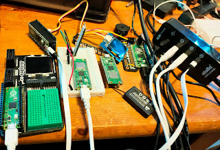
I had to dig out an extra USB hub to drive all the projects I showed!


Missed it? Don't worry!

You can watch a recording on YouTube:


Wednesday, 3 August 2022

Connect the Raspberry Pi Pico to an OLED using Grove breakouts

In this short article you'll learn how to make and use a compact, inexpensive adapter that will allow you to connect a Raspberry Pi Pico/PicoW to Grove I2C peripherals. With a Grove to Stemma QT/Kwiic adapter cable, you can also connect your Pico/PicoW to Adafruit and Sparkfun I2C devices.

You'll laso learn a useful hack that lets you connect the 2mm spaced Grove adapters to a 0.1" spaced (2.54mm) pcb.

Grow with Grove

Regular readers will know I love breakout boards.

One of the projects that I've been working on is a Raspberry Pi Locator. It reads updates from the @rpilocator RSS feed, and it tells you when and where Raspberry Pi stock is available. The Pico W will sound a buzzer when there's stock around, but it would be great if it could tell you which stores had the Pis. On OLED display would keep things compact, and I thought I'd hook one up.

Seeed studios have a great range of Grove breakouts with an easy-to-use connection system, and I knew I had some Grove-compatible I2C OLEDs in my parts stock.

Then I realized I'd need an adapter to connect the Pico to the OLED.

I have a few of Pimoroni's Pico proto boards, and I wondered if I use one as a base for a Grove connector.

After a few false starts I had a soldered connector. Soldering the board is a little fiddly, but it's not too bad if you add the components in the right order.

Here's the parts list:

1 Pimoroni Pico proto board. 2 x 20 way 0.1" female headers 2 x 2.7K ohm resistors. Anything from 2.2k to 5.6K would work just as well 1 Grove connector Tinned copper wire and white, yellow, red and black hookup wire.

Here's the schematic:

image

Begin by soldering two lots of bridge wires between successive strips of the Pico proto.

Next, cut and solder wires from the proto inner edge of the proto to the relevant strips,

There are four of those connections.

The white wire caries SDA, the I2C data signal. The yellow wire carries SCL, the I2C clock signal. The red wire carries 3.3 volts. The black is 0v (Ground).

After that, solder the Grove connector. Make sure you have it the right way around! Since its legs are 2mm apart, you need to splay them out slightly to fit the 0.1" spacing of the Pico proto.

Finally, solder the female headers to the board. Make sure the board is the right way up!

The easiest way to solder female headers is to use a breadboard with two rows of male headers plugged in. Then push the female headers onto the th male header pins and place the Pico proto board on top of the female headers.

Now it's easy to solder the board to the female headers.

image

Time to test the board!

Checking I2C

Connect the OLED (or whatever I2C device you plan to use) using a standard Grove cable.

Next, run the following program on your Pico.


# We're using I2C0 with SDA on Pin 0, SCL on pin 1

import machine
i2c = machine.I2C(0, scl=machine.Pin(1), sda=machine.Pin(0))

print('Scanning')
devices = i2c.scan()

if len(devices) == 0:
  print("No i2c devices found!")
else:
  print('%d i2c device(s) found:'% len(devices))

  for device in devices:  
    print("address: %d - 0x%X" % (device, device))

It should list all the I2C devices it finds on the Pico's I2C bus 0.

I used Grove 128x128 pixel monochrome OLED based on the SH1107 display. After a little searching I found a MicroPython driver for it.

I installed the driver on the Pico and ran this test:


import sh1107
import machine


i2c = machine.I2C(0, scl=machine.Pin(1), sda=machine.Pin(0))
oled = sh1107.SH1107_I2C(128, 128, i2c)

oled.text('MicroPython', 10, 0)
oled.text('I2C + Pico', 10, 16)
oled.text('+ Grove', 10, 32)
oled.show()

And voila:

image

Monday, 1 August 2022

Simple, repeatable deployments in a MicroPython environment

Have you ever suffered from "It works on my machine"?

Most of us have, as users (well, it doesn't work on mine!") or as developers ("what have I done wrong this time?". 

The cause is almost always down to something that's on the developer's machine that they have forgotten about, but make use of. That something doesn't get included in the installation process, so users may not have it installed.

There's a great way to avoid that.

Testing an installation process if you have an OS

If the software you're developing runs under an Operating System, run the installation in a freshly-created virtual machine. That will ensure that you start without somethings installed. You'll only have the software that's specified in your installation process.

If that works, you're in good shape.

What about installing MicroPython software on devices like the Raspberry Pi Pico?

Testing an installation process for MicroPython projects

A comparable deployment process has three stages. You need to

  1. Wipe the MicroPython file system completely
  2. Install a known version of MicroPython
  3. Install the application code
You can find software to do stages 1 and 2 on GitHub
It's called mp-installer.

The README file has instructions for installation and use.

At present it only works on Linux, including Raspberry Pi OS on the Pi or other hardware.
I'll get it working on Windows and/or Mac/OS if I can find a helpful collaborator!

Installing the application code

If your application consists of one or two files you can install the code manually using Thonny.

If you want an automated process, or have many files to install, there's a great alternative.

Use mpremote to install MicroPython files

mpremote is a really useful utility written by the MicroPython team.

You call it from the command line. You can use it to move files to and from the Pico, run files, execute MicroPython commands. You can even force the Pico into boot-loader mode if you need to update the MicroPython interpreter.

You'll find instructions for installing and using mpremote here.

Here's a script that installs a complete application:

#!/usr/bin/env bash
cd ../src
mpremote cp secrets.py :secrets.py
mpremote cp network_connection.py :network_connection.py
mpremote cp -r mp/ :
mpremote cp -r pi_finder/ :

A repeatable, reliable process

You'll find that running mpremote in a script is a great way to install all the files your application needs.

If you first run mp-installer.py with the nuke option, you'll have a repeatable automated installation process.

That way you'll be confident that your users will get all the software they need to run your application.