Pages

Thursday, 25 August 2022

How to write reliable tests for Python MQTT applications

More and more IoT applications use MQTT. It's a simple and very useful messaging framework which runs on small boards like the Raspberry Pi Pico as well as systems running under Linux, MacOS and Windows.

I recently decided to add some extra functionality to Lazydoro using MQTT. The code seemed to work when run manually but I had a lot of trouble getting my automated tests working. It took quite a while to understand the problem, but the fix was simple.

Intermittently failing tests are bad

In the end-to-end test that was causing the problem, the code simulated the start of a pomodoro session and then checked that the correct MQTT message had been  sent. The test usually failed but sometimes passed. When I manually ran a separate client that subscribed to the message stream I could see that the right messages were being sent.

Intermittently failing (or passing) tests are a nuisance. They do nothing to build confidence that the application under test is working reliably, and they are no help when you're refactoring. You can never be sure if the tested fail because you made a mistake in the refactoring, or was it just having one of its hissy fits?
Solving timing problems

Intermittent failures like this are often due to timing issues. It's tempting to solve them by adding delays to the testing code, but this is prone to problems. Too short a delay, and the tests still fail from time to time; too long a delay, and the tests become burdensome to run.

The solution is simple; write your test so that it polls to see if the expected condition is true, and set a  timeout so that it will only expire if the test is going to fail.

Before the test checks that the correct message has been sent, it waits until there is a message to check.

Here's the code that waits:


 def wait_for_message(self, tries = 100, interval = 0.01):
        for i in range(tries):
            if len(self.messages()) > 0:
                return
            sleep(interval)
        raise ValueError('waiting for message - timed out')
Now the tests run reliably.

You can see the entire Test Client code here.

Thursday, 11 August 2022

How can you make your Pico/Pico W project portable?

In this article you'll learn how to solder the Pimoroni Lipo Shim for Raspberry Pi Pico/Pico W and use it to power your project from a single LiPo battery. You'll also discover a problem, and a solution, if you want to check the battery level remotely.

Some Pico W projects need to work anywhere. Wi-Fi takes care of the connectivity, but the projects need battery power to make them truly portable.

If you're building a portable project you'll find the Pimoroni Lipo Shim for Pico is a great solution. Here's how to attach and use it.

Powering the Pico

While you're writing the software for your Pico or Pico are you'll be using a USB cable to linking it to your host. Once your hardware and software are working you may want to free the Pico from its umbilical cord.

The Pico can be powered from a battery; it's very adaptable, working off an input voltage that can range from 1.8 to 5.5 volts.

The Pimoroni Lipo Shim for Pico takes advantage of that. It lets you power your project from a compact LiPo battery, and you can recharge the battery via USB when it needs it. You can even use the Pico while the battery is charging.

There are lots of suitable batteries available, from Pimoroni and others, but my current favourite is the Pimoroni Galleon; its rugged case reduces the risk of crushing or puncturing the LiPo.

So how do you hook up the LiPo shim to the Pico it's powering?

Pimoroni suggest two options.

Connecting the Pico

Both options involve some soldering. One is simple; the other, Pimoroni suggest, is suitable for advanced solderers. You can connect the Pico to other components via female header sockets or male header pins.

The simple option

You want to connect two layers of PCB, one for the Pico and one for the Shim. You can use stacking female headers like this:

image

Image courtesy of Pimoroni.

You get a bonus (sockets on the top of the Pico, giving you extra connection options), but there are two disadvantages: your project is now quite a bit bigger, and you may find it fiddly to press the bootsel button if you need to.

There's an easy fix to the bootsel issue; you can use mpremote's bootsel command, or run machine.bootsel() from a REPL.

If space is a problem, you have another option.

For advanced solderers

From the Pimoroni site:

"Alternatively, if you're ambitious in the ways of experimental soldering, you can try soldering the Pico and the SHIM both to the short end of your header, back to back. This method makes for a much more slimline Pico/SHIM package which works nicely with Pico Display, but you'll need to make sure your solder joints make good contact with the pads of both boards and the header."

Here's how you do it, in words and pictures.

Step 1

Push 2 rows of 20-pin male headers part way into a breadboard and place the shim on top. Make sure that the

button of the shim is located below the shim and below where the USB connector of the Pico will be.

image

image

Step 2

Lay the Pico/PicoW on top of the shim

image

Step 3

Solder the corners of the Pico to the headers and check that everything is correctly aligned.

If not, it's fairly easy to melt the solder on the relevant corner and fix the alignment.

image

Step 4

You may want to check the underside of the Pico as well as the top.


Step 5

Now solder more of the header pins, filling the castellations at the side of the Pico and shim with solder.

image

Step 6


If all is well you should see a white LED, showing that the Pico is powered, and a red LED, showing that the battery is charging.

NB: You may need to push the button on the end of the shim to turn the power on.

Well done! You are now an official advanced solderer :)

Checking the battery voltage

If you're using a Pico you can easily use an OLED display to show the state of the battery. There's a useful program to do that on the Pimoroni website, but it won't work for the PicoW without a change. That's because it uses ADC29 (also known as ADC3) to monitor the Vsys voltage.

You can do that on the Pico W, but you need to pull P25 high which disables wireless. Since I wanted to use MQTT over a wireless connection to monitor the battery, I had to find an alternative solution.

A couple of the projects I had in mind used two of the three normal ADC pins on the pico, but none used all three., If your project doesn't need three Analogue inputs, you can use one to monitor the battery voltage.

That needs a little care, as the GPIO pins on the Pico (including the analogue pins) should not be connected to more than 3.3 volts. A fully charged Lipo might be outputting 4.2 volts, which would damage the analogue pin.

Fortunately there's an easy solution.

Using a voltage divider.

You can use a voltage divider to reduce Vsys to a safe voltage. I used two 10K ohm resistors, but 100K would be better, as that would reduce battery drain.

Then you can safely read the adc output and convert it to a voltage. Remember to multiply it two to compensate for the divider!

Here's the breadboard layout for the divider:

image

and here's the schematic:

image

The code

# This example shows how to read the voltage from a LiPo battery
# connected to a Raspberry Pi Pico via the Pimoroni LiPo shim for Pico


# secrets.py should contain your network id and password in this format:

"""
SSID = 'your Wi-Fi network id'
PASSWORD = 'your Wi-Fi password'
MQTT_HOST='broker url'
"""


from machine import ADC, Pin
import time
import random
import network_connection
from umqtt.simple import MQTTClient
from secrets import SSID, PASSWORD, MQTT_HOST

# connect to wifi
# this may take several seconds

network_connection.connect(SSID, PASSWORD)
print('connected')


CLIENT_ID = 'pico-lipo-monitor-%d' % (1000 + random.randrange(999))
mc = MQTTClient(CLIENT_ID, MQTT_HOST, keepalive=3600)
mc.connect()

adc2 = ADC(28)
conversion_factor =  2 * 3.3 / 65535

while True:
    voltage = adc2.read_u16() * conversion_factor
    message = 'Lipo voltage: %f' % voltage
    mc.publish('lipo', message)
    time.sleep(60)

Summary

That's how you can connect the Pimoroni Lipo shim for Pico and the Pico W, and how you can then monitor the LiPo battery voltage.

I'll be publishing the hardware and software details of the weather station project in my forthcoming guide to the Pico W. Read more details here.

Tuesday, 9 August 2022

Raspberry Pi PicoW projects on Tom's Hardware PiCast

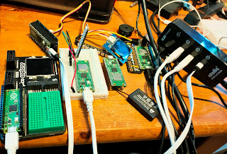
A few days ago I was asked to present some of my Raspberry Pi Pico W projects on the PiCast from Tom's Hardware.

Editor Avram Piltch (@geekinchief) was the super-friendly host as usual, and Les Pounder (@biglesp) told us about his Pico W-based webserver. Raspberry Pi expert Ash Hill added to the fun.

Ash edits Tom's hardware's monthly Best Raspberry Pi Projects feature - always worth a read.

Pico W projects a-plenty

I had to dig out an extra USB hub to drive all the projects I showed!


Missed it? Don't worry!

You can watch a recording on YouTube:


Wednesday, 3 August 2022

Connect the Raspberry Pi Pico to an OLED using Grove breakouts

In this short article you'll learn how to make and use a compact, inexpensive adapter that will allow you to connect a Raspberry Pi Pico/PicoW to Grove I2C peripherals. With a Grove to Stemma QT/Kwiic adapter cable, you can also connect your Pico/PicoW to Adafruit and Sparkfun I2C devices.

You'll laso learn a useful hack that lets you connect the 2mm spaced Grove adapters to a 0.1" spaced (2.54mm) pcb.

Grow with Grove

Regular readers will know I love breakout boards.

One of the projects that I've been working on is a Raspberry Pi Locator. It reads updates from the @rpilocator RSS feed, and it tells you when and where Raspberry Pi stock is available. The Pico W will sound a buzzer when there's stock around, but it would be great if it could tell you which stores had the Pis. On OLED display would keep things compact, and I thought I'd hook one up.

Seeed studios have a great range of Grove breakouts with an easy-to-use connection system, and I knew I had some Grove-compatible I2C OLEDs in my parts stock.

Then I realized I'd need an adapter to connect the Pico to the OLED.

I have a few of Pimoroni's Pico proto boards, and I wondered if I use one as a base for a Grove connector.

After a few false starts I had a soldered connector. Soldering the board is a little fiddly, but it's not too bad if you add the components in the right order.

Here's the parts list:

1 Pimoroni Pico proto board. 2 x 20 way 0.1" female headers 2 x 2.7K ohm resistors. Anything from 2.2k to 5.6K would work just as well 1 Grove connector Tinned copper wire and white, yellow, red and black hookup wire.

Here's the schematic:

image

Begin by soldering two lots of bridge wires between successive strips of the Pico proto.

Next, cut and solder wires from the proto inner edge of the proto to the relevant strips,

There are four of those connections.

The white wire caries SDA, the I2C data signal. The yellow wire carries SCL, the I2C clock signal. The red wire carries 3.3 volts. The black is 0v (Ground).

After that, solder the Grove connector. Make sure you have it the right way around! Since its legs are 2mm apart, you need to splay them out slightly to fit the 0.1" spacing of the Pico proto.

Finally, solder the female headers to the board. Make sure the board is the right way up!

The easiest way to solder female headers is to use a breadboard with two rows of male headers plugged in. Then push the female headers onto the th male header pins and place the Pico proto board on top of the female headers.

Now it's easy to solder the board to the female headers.

image

Time to test the board!

Checking I2C

Connect the OLED (or whatever I2C device you plan to use) using a standard Grove cable.

Next, run the following program on your Pico.


# We're using I2C0 with SDA on Pin 0, SCL on pin 1

import machine
i2c = machine.I2C(0, scl=machine.Pin(1), sda=machine.Pin(0))

print('Scanning')
devices = i2c.scan()

if len(devices) == 0:
  print("No i2c devices found!")
else:
  print('%d i2c device(s) found:'% len(devices))

  for device in devices:  
    print("address: %d - 0x%X" % (device, device))

It should list all the I2C devices it finds on the Pico's I2C bus 0.

I used Grove 128x128 pixel monochrome OLED based on the SH1107 display. After a little searching I found a MicroPython driver for it.

I installed the driver on the Pico and ran this test:


import sh1107
import machine


i2c = machine.I2C(0, scl=machine.Pin(1), sda=machine.Pin(0))
oled = sh1107.SH1107_I2C(128, 128, i2c)

oled.text('MicroPython', 10, 0)
oled.text('I2C + Pico', 10, 16)
oled.text('+ Grove', 10, 32)
oled.show()

And voila:

image

Monday, 1 August 2022

Simple, repeatable deployments in a MicroPython environment

Have you ever suffered from "It works on my machine"?

Most of us have, as users (well, it doesn't work on mine!") or as developers ("what have I done wrong this time?". 

The cause is almost always down to something that's on the developer's machine that they have forgotten about, but make use of. That something doesn't get included in the installation process, so users may not have it installed.

There's a great way to avoid that.

Testing an installation process if you have an OS

If the software you're developing runs under an Operating System, run the installation in a freshly-created virtual machine. That will ensure that you start without somethings installed. You'll only have the software that's specified in your installation process.

If that works, you're in good shape.

What about installing MicroPython software on devices like the Raspberry Pi Pico?

Testing an installation process for MicroPython projects

A comparable deployment process has three stages. You need to

  1. Wipe the MicroPython file system completely
  2. Install a known version of MicroPython
  3. Install the application code
You can find software to do stages 1 and 2 on GitHub
It's called mp-installer.

The README file has instructions for installation and use.

At present it only works on Linux, including Raspberry Pi OS on the Pi or other hardware.
I'll get it working on Windows and/or Mac/OS if I can find a helpful collaborator!

Installing the application code

If your application consists of one or two files you can install the code manually using Thonny.

If you want an automated process, or have many files to install, there's a great alternative.

Use mpremote to install MicroPython files

mpremote is a really useful utility written by the MicroPython team.

You call it from the command line. You can use it to move files to and from the Pico, run files, execute MicroPython commands. You can even force the Pico into boot-loader mode if you need to update the MicroPython interpreter.

You'll find instructions for installing and using mpremote here.

Here's a script that installs a complete application:

#!/usr/bin/env bash
cd ../src
mpremote cp secrets.py :secrets.py
mpremote cp network_connection.py :network_connection.py
mpremote cp -r mp/ :
mpremote cp -r pi_finder/ :

A repeatable, reliable process

You'll find that running mpremote in a script is a great way to install all the files your application needs.

If you first run mp-installer.py with the nuke option, you'll have a repeatable automated installation process.

That way you'll be confident that your users will get all the software they need to run your application.

Saturday, 30 July 2022

Seven secrets of the Raspberry Pi Pico's success

The Pi Pico sold well; the Pico W has sold out several times since its launch.

With two million units planned for production this year, the Pico shortage will be temporary, but it's a sign that the new Pico W is going to repeat the amazing success of the original Raspberry Pi.

Pico W

Why is it selling so well?

What's the secret?

Yesterday I jointed a group of friendly and knowledgeable enthusiasts for  an online meeting of the Melbourne MicroPython Meetup.

It's not just a user group. Damien George gave a talk about the Rapsberry Pi Pico W. Damien is the creator of MicroPython, and he was responsible for the MicroPython port with Wifi support. The software was available on the day that the Pico W launched.

In the discussion that followed, several of us speculated about the secret sauce that made the Pico/Pico W so successful.

We concluded that there was no single factor, but that several features combined to make them so attractive.

Seven key features

What helped to catapult the Pico and Pico W to instant success?

First: the Raspberry Pi brand. With over 40 million Pis in the hands of Makers, Programmers, Learners, Teachers and Entrepreneurs, the Raspberry Pi name is widely known, respected and trusted.

Second: Community. the Pico family is supported by a huge Raspberry Pi community of Makers, Hackers, Journalists and Vendors.

On the day of its launch companies like Pimoroni, Adafruit and the Pi Hut offered the Pico W for sale and  announced their own add-on products.  The Pico W sold quickly.

By the next day enthusiasts had started to share their exploration of the Pico W!

Tom's Hardware publicised the product from the day of its launch and was quick to share projects as they were announced.

The July 2022 issue of the MagPi magazine has articles about Pico projects, and reviews of  newly announced third party products.

Third: Great documentation, available at launch. Raspberry Pi's documentation is written by Alasdair Allen. He's uniquely qualified. He's a been a physicist, a hardware hacker and a journalist. His documentation is readable, clear and accurate, and he's quick to respond to feedback.

Fourth: Great software, available from the start.

With a full-featured, well-documented MicroPython port available from day one, the Pico W made it really easy for us to explore its potential.

Pico W strip
Fifth: Great for making new products. The castellations on the Pico and Pico W allow them to be soldered directly onto PCBs.

Picos are available in quantity, in strip packaging, as is the RP2040 chip on which they are based.

Sixth: PIO (Programmable I/O) is an amazing feature of both the original Pico and the W.

PIO has enabled all sorts of capabilities; an HDMI interface, a VGA interface, and other specialist protocols, all implemented in software

Seventh: Availability. While the Pico W has sold out a couple of times, stocks have quickly been replenished. Global chip shortages have impacted the availability of many products, including the Raspberry Pi Model 4, but the Pico has been essay to find online.

What are the Pico's competitors?

There are hundreds of similar products, but the main competitors of the Pico are
  1. Boards from other manufacturers that use the same chip - the RP2040. Boards are available from dozens of vendors, including Adafruit, Pimoroni and Arduino. Many of these have great extra features, but most cost significantly more than the $4/$6 of the Pico and Pico W.
  2. Boards from the Arduino family. The Arduino has a large and loyal following, but the original products lack the memory to support MicroPython, and more recent products are significantly more expensive.
  3. Boards based on the ESP 8266/32. These have a large following, and they are available at a very competitive price. I'm sure they will continue to hold a significant share of the market, but their market is fragmented and the boards attract much less media coverage than the Pico.

So what's the future?

The range of Pico-based projects and products is growing fast. Eben Upton (CEO of the commercial arm of Raspberry Pi) says they expect to make 2 million units this year, ant it looks as if demand will match or exceed that. The Pico is affordable, powerful, fun and available. It's a great platform.

I'm currently working on a free guide to the Pico W. Keep an eye on this blog, or follow @RAREblog in Twitter for more information.


Monday, 18 July 2022

Make your own strip-board breakout boards

A useful trick for Makers

In this article you'll see when you should build your own breakout boards, and you'll learn a useful trick to use when making them.

Breakout boards rock

Digital Makers can often make projects faster by using breakout boards.

A breakout board is a small but useful module that you can use to compose your project. There are hundreds of breakout boards available. Many are based on tiny SMD chips that are tricky to solder. You can save time and reduce the risk of mistakes by buying a ready-made breakout board.

Here's an Adafruit breakout board I used in the Raspberry Pi version of Lazydoro.

image

Of course, you can only buy a ready-made board if you can find one that does what you need,

If there isn't, consider making one!

Why bother with self-built breakouts?

Why not just put everything you need on the main project board?

There are advantages to a design that uses pluggable modules. You can usually test the module on its own, and there's a good chance that you can re-use the model (or at least the design) in future projects.

Hardware and software developers have been doing this for decades. Well-designed hardware and software modules reduce coupling, increase cohesion, and increase quality.

Here's a concrete example from a current project.

A buzzer module.

One of my projects (lazydoro) needed a buzzer.

The project is based on the Raspberry Pi Pico W, so digital outputs are limited to 3.3 volts. Some active buzzers will work at that voltage, but they sound a bit feeble. I needed to hear the buzzer in the next room, so I wanted to drive it at 5 volts.

I decided to build a module.

The module design

The circuit is simple. It uses an inexpensive BC337 NPN transistor as a switch. A 3.3 volt control signal applied to the base of the transistor runs the switch on, reducing the output voltage to just over 0 volts. That results in a 5 volt potential difference across the buzzer, which then buzzes loudly.

Here's the schematic.

image

NB: In the schematic, power, ground and the signal come in on the right!

Mark 1 - oh, dear

I built the module on a small piece of strip-board. Since you can only solder strip-board on the copper side of the board, I soldered a 3-way female header on the module and a 3-way male header on the main board.

image

It worked, but it didn't look very pretty in place.

image

Mark 2 - the trick

Luckily I remembered an old trick which resulted in a much neater version.

If you solder header pins without modding them the pins are too short to plug into a female header.

Luckily, you can push the plastic to the top of the pins so they look like this:

image

Now you can solder them to strip-board and the pins are long enough to work.

Here's the new module:

image

and here's the strip-board design. As you can see, the design fits on a standard 9-strip board, and you don't need to cut any of the strips.

image

I added a female header to the main board and inserted the new module. Here it is in place. It works perfectly and looks much better now the buzzer is on top!

image

Summary

Breakout boards are a great times-saver. If you can't find one that does what you want, it's often easy (and satisfying) to make your own.

If you're using strip-board you can easily adapt male headers to that you can solder them to the copper side of the strip-board.

Sunday, 17 July 2022

Ports and Adapters - Struggling back to Beginner's Mind

I have to admit it: I've been struggling over the last two days. 

I'm working on a write-up of a Walking Skeleton for Lazydoro, together with sample code for its Ports and Adapters architecture.

I often create a Walking Skeleton at the start of an application. Lazydoro is now in its fifth version,  there's already a finished working version, and it's difficult to 'un-know' how it evolved. Trying to create what I might have written at the start has been quite a challenge

The process has been valuable, though. I think I understand Ports and Adapters better through working on my sample code and explanation, and it's had another benefit.

I've set up an automated deployment process which I'll be able to use for future MicroPython projects.

Automating deployment

Some applications can be deployed as a single file, but small modules are easier to read and test. lazydoro now consists of 9 files in a three-directory tree, and deploying a new version manually has become a real pain and is prone to error.

The new process uses a gist on GitHub which deletes all the files from a MicroPython-based board. It's always possible that your code relies on a file that you deployed a while back but have now forgotten about - a common cause of 'It works on My Machine'. 

Deployment to an empty file system is the safest way of avoiding that.

There's more to the deportment task than that, and I'm documenting the whole malarkey.

What's coming

I'm not sure how soon I'll have all the sample code ready, but you'll get to see three things:

  1. The automated deployment process
  2. The Walking Skeleton, and what you risk without one
  3. Ports and Adapters in an Embedded Application, and how that architecture helps with unexpected change.
Meanwhile I will be posting a short article about a simple technique for making stack-able breakout boards using strip-board. It's a very simple trick I forgot to apply to lazydoro until this morning; the buzzer break-out board now look much neater. 


Friday, 8 July 2022

Raspberry Pi Pico W project plans

Please help me choose!

The announcement of the Raspberry Pi Pico W has opened up a huge range of fun, exciting projects.

image
Pico W in the cloud
I've a long list of candidates, and I'm hoping for advice about which ones have the widest appeal.

The first project is a shoo-in, not least because it's almost finished. I'll tell you about that shortly. I have seven other projects pulling for my attention, and I'll give you a quick introduction to each. Then I hope you can help me chose which to do next, or even suggest an alternative.

I'll open up polls on Twitter and Facebook, but I'd also welcome feedback on this blog.

Project number One

If you're a regular reader of the RAREblog you will already be familiar with Lazydoro, my automated Pomodoro timer. The current version is now running well, but it's based on a Raspberry Pi Zero. I'm migrating the project to the Pico W for two reasons:

  1. I want to keep a daily log of my Pomodoros, so I need wifi access
  2. A new Raspberry Pi is a rare thing at the moment, because of the chip shortage.

In contrast, the supply of Pico Ws is fine. If you want to build your own Lazydoro you'll find it easy to get all the necessary hardware, and you'll pay less for it!

I'll blog about the hardware and software as soon as I've finished the migration - but after that I wonder what to build next.

After that?

These are the next projects I have in mind, in alphabetical order.

All of them are simple and inexpensive.

Which would appeal to you? And what other projects would you like me to build?

Digital Callipers

I've had a set of Digital Callipers for ages, and I love them.

image
digital callipers

They work well, but I find it annoying having to manually record dimensions. I've used the callipers to capture the sizes of new boards that I was adding to the library for Breadboarder.

What I'd like, ideally, is to be able to press a button on the callipers that captures a measurement and simultaneously triggers a photo of what's being measured.

There's an article on Hackaday that shows how to capture measurements with a PIC micro. I'm sure I can do it with the Pico.

Logic Analyzer

I have several items of test equipment that I use to track down issues with I2C and Serial comms, but they take a while to set up and the interface is never quite what I want.

I like the idea of a web-based interface that I can tailor to my needs. I could use the GPIO pins on a Pico W to track digital signals, but if I used an MCP23S17 I could monitor up to 16 signals in parallel at the speed of SPI.

I know I'd find that useful. Would you?

The Microwriter

Back in the early 1980s word processing was all the rage. If you wanted to write text on the move your options were limited. One popular solution was a chording keyboard device called the microwriter

The original microwriter
micowriter

Rumour has it that the microwriter was particularly popular with James Bond's colleagues. In the 1980e chaps like James couldn't type but apparently Q convinced them that the microwriter was cool to use - a sort of Typist's Aston Martin.

I'd love to create an updated microwriter. You could display the text you type on a cheap monochrome OLED, store the text in flash and use wifi to upload it to your laptop or workstation.

The Intelligent Breadboard

This is another project I've had on hold for ages.

The idea is simple: connect the strips of a breadboard to something which can montor (and perhaps set) the voltage of each strip.

It's a simple form of Automatic Test Equipment (ATE).

The first version of TIB (The Intelligent Breadboard) would have two MCP23S17s connected to the strips of a mini breadboard with 170 tie points.

image
mini breadboard

Later versions could add analogue voltage measurement and connect to a larger board. You could even program TIB to check your wiring step-by-steo when prototyping a new project.

A Web-based Oscilloscope

Years ago, when the first mbed board came out, I wrote a project that created a web-page showing a varying voltage. I used svg to generate the graphics. It worked surprisingly well. Time to update that for the Pico W?

The first version would be for audio frequency signals only, but it would be interesting to see how rapidly one could capture analogue signals. I'd want to wrap some high-performance ome C code as an .mpy file. I've not tried that, and it would be a useful skill to learn.

SLAMbot

SLAMbor is a mobile robot. Not one that slams into things, but one that does SLAM: Simultaneous Location and Mapping.

You'd control the robot from your phone, and it would use a set of 8 VL53L0X ToF sensors to build a map of its environment as you drove the bot around a room.

Weather Station

I'd love to build a web-connected weather station around the BME280. I'd also like an anemometer to measure wind speed. I've recently come across a couple of promising designs that could be built without a 3D printer.

Over to you

I'm looking forward to a lot of Pico W fun over the next few weeks!

I'll post a list of the projects on Twitter and ask for your vote. It will have to be a pair of polls as I think Twitter limits us to 4 choices.

Alternatively, you can let me know what you'd like to see as a comment on this blog.

Tuesday, 5 July 2022

Lazydoro is working again!

Yesterday things looked tricky.

I realised this morning that I could easily fix the problem I've been having with lazydoro and my new chair.

Doh! All it took was an adjustment to the distance threshold.

Lazydoro is now sitting by my keyboard and keeping a watchful eye on me.


lazydoro back at work

Next steps: keep a log of Pomodoros completed/broken.


Monday, 4 July 2022

Lazydoro Mk 3 - lots of automated tests for a simple design

At the end of  yesterday's post lazydoro was running on a Pi zero still not working reliably.

In November 2021 I worked on Ness Labs' Write a book in 30 days challenge.

I had to rely on a web-based Pomorodo timer, and thought I'd have another try at the lazydoro project.

I decided to rewrite lazydoro from scratch.

Lazydoro needs to do four things.

  1. It needs to know when I arrive at or leave my desk
  2. It needs to keep track of passing time
  3. It needs to know where I am in a Pomodoro cycle
  4. It needs to provide feedback to keep me on track.

To make lazydoro easy to test I used a variant of the Ports and Adapters architecture. (Ports and Adapters is sometimes called Hexagonal Architecture).

I first came across it in an article by Alistair Cockburn, and it made a lot of sense. It's also featured in the GOOS book: Growing Object Oriented Software Guided by Tests.

Simple architecture

Here's the architecture for lazydoro:

image

At the centre is the application model: the Pomodoro object. That contains code that keeps track of where I am in the Pomodoro Cycle. It's a state machine, and it changes state based on my presence or absence and the passage of time.

The Pomodoro model gets inputs from a ClockWatcher.

The ClockWatcher gets a tick that tells it time has passed. It then asks the rangefinder how close the nearest object is, and from that it works out whether I've just arrived at or left my desk and sends a message to the Pomodoro object as necessary .

As the Pomodoro tracks the various states (waiting to start, in a Pomorodo, waiting for me to begin a break, on a break, or waiting for me to return). it updates the Display, turning LEDs on or off and sounding the buzzer as appropriate.

The great advantage of that  approach is that I can easily test the application. I can send a message pretending that a second has passed as often as I like. That's really helpful because it allows me to run a test much faster than real time. A real Pomodoro cycle takes 30 minutes: 25 minutes of work and a 5-minute break. I can simulate a full cycle in under a second if my fake clock ticks fast enough.

Mock Objects

The automated tests use Mock Objects to represent the RangeFinder and Display.

As a result, the tests are simple and expressive. Here's the test code for a full Pomodoro cycle:

def test_tracks_full_pomodoro(self):
    # main success scenario
    self.person_absent()
    self.wait(seconds=1)
    self.check_leds_are_off()
    self.person_present()
    self.check_leds_are_off()
    self.wait(seconds=10)
    assert_that(self.display, shows_only(BLUE))
    self.wait(minutes=24)
    assert_that(self.display, shows_all(BLUE))
    self.wait(minutes=5)
    assert_that(self.display, shows_all(RED))
    self.person_absent()
    self.wait(seconds=20)
    assert_that(self.display, shows_only(GREEN))
    self.wait(minutes=1)
    assert_that(self.display, shows_only(GREEN, GREEN))
    self.wait(minutes=1)
    assert_that(self.display, shows_only(GREEN, GREEN, GREEN))
    self.wait(minutes=1)
    assert_that(self.display, shows_only(GREEN, GREEN, GREEN, GREEN))
    self.wait(minutes=1)
    assert_that(self.display, shows_only(GREEN, GREEN, GREEN, GREEN, GREEN))
    self.wait(minutes=1)
    self.check_leds_are_off()
    self.person_present()
    self.wait(seconds=20)
    assert_that(self.display, shows_only(BLUE))

Success at last?

It worked well for weeks, and I used lazydoro every day.

And then it stopped working.

What went wrong?

The code was fine. The problem was physical.

I got a new chair for my study.

It had much better support for my back, but lazydoro's ToF sensor sometimes thought the chair was me! It picked up a reflection from the back of the chair, and it sometimes thought I was at my desk doing a Pomodoro even when the chair was empty.

A new beginning

I needed a new approach.

I decided to ask for help in one of the Facebook groups I belong to, and got lots of interesting suggestions.

Tomorrow I'll reveal what happened next.

Sunday, 3 July 2022

Lazydoro migrates to the Pi

In the previous blog post I described cushadoro and its successor, lazydoro Mk 1.

That was the first version of lazydoro, implementedin CircuitPython and based on the Adafruit Trinket M0. Today I'll describe the next stage of the project, a Raspberry Pi-based version.

I made real progress but, as you'll see, lazydoro was still not quite good enough.

Lazydoro needed unit tests

At the point were we left the project the Python code had become a little complicated. I thought I ought to do more automated testing.

It's possible to do that on CircuitMpython devices like the Trinket M0, but it's a lot easier if you canuse the standard Python libraries, including Python's unittest and mock frameworks.

I decided to migrate the project to a Raspberry Pi.

Moving to the Raspberry Pi

image
Explorer HAT prototype
At the time I migrated the project I had just fallen in love with Pimoroni's brilliant Explorer HAT pro. The HAT has loads of useful peripherals, and needs no soldering, so it's great for learning and for rapid hardware protoyping.

I liked the Explorer HAT so much that I wrote a book about it!

The first version of Lazydoro Mark 2 used an Explorer HAT, a VL53L0X sensor and a buzzer for feedback.

Migrating the code with Adafruit Blinka

Adafruit's VL53L0X library is written for CircuitPython, but the clever folk at Adafruit have come up with a library for the Pi called adafruit-blinka.

Blinka allows you to use Adafruit's CircuitPython's device libraries on a Raspberry Pi or a Jetson Nano. I found I could move the sensor code from the Trinket to the Pi without change.

I did make one change, though, taking an opportunity to enhance the hardware.

Adding the Pimoroni Blinkt!

image
Pi zero version with Blinkt!
I replaced the Trinket's single NeoPixel with a Pimoroni Blinkt! display.

The Blinkt! has a bank of 8 multi-colour NeoPixels. There's a Pimoroni library that can set the colour and brightness of each display.

That allowed me to show how much time had passed during a Pomodoro or a break.

The project doesn't need a lot of computing power, so I decided to run it on an inexpensive Raspberry Pi Zero.

Once I had a working prototype I transferred the design to an Adafruit perma-proto bonnet.

That was good enough to demonstrate.

Featured on Hackaday!

I showed it off at a Raspberry Pint Meetup, and posted the project on Hackaday.io. To my delight it got featured, and quite a few people showed interest.

I might have stopped there, but I didn't.

The Mark 2 version was good, but not quite good enough.

Lazydoro - usable but not ideal

I used Mark 2 intermittently, but it wasn't perfect.

The ToF sensor still returned occasional spurious readings. Some were easy to fix.

The sensor sometimes returns a distance of 0 instead of the 8191 reading that means 'out of range'.That looked like an off-by-one error in the library or the hardware! I wrote a simple fix for that problem, but I found I still got occasional spurious readings.

I found the necessary change was harder that I'd hoped. I made a few attempts, but I used lazydoro less and less, and I eventually accepted the frustrations of using a web-based timer.

In November last year I started work on a new book: Give Memorable Technical Talks.

I did a lot of Pomodoro-based writing, and I longed for a better Pomodoro timer.

Next - Lazydoro Mark 3

Want to know how the search for a timer went? Look out for more revelations in the next thrilling episode!

Saturday, 2 July 2022

The Lazydoro story - Part 1

The Lazydoro

Lazydoro is potentially the most useful project I've built.

I use the Pomodoro method when I am writing or coding. It keeps me focused, and makes it easy for me to maintain progress. The Pomodoro technique involves working for 25 minutes without interruption, followed by a 5-minute break away from your desk. It helps with productivity, and it's good for your health.

There's just one problem. You need to remember to start a Pomodoro timer!

Using a timer

When I first started using the technique I tried using a web-based app to keep track of time.

Sometimes I remembered to use it, but sometimes I forgot. If I was deeply absorbed in what I was doing I lost track of time and failed to take my break. After a few days of that my mood and my knees suffered!

I tried building some hardware to make the Pomodoro technique easier to use.

Cushadoro
image
Cushadoro

I started the project back in 2015. I called that version cushardoro - an Adafruit trinket attached to a resistive pressure sensor located in a cushion on my study seat!

It worked after a fashion, but it had several practical drawbacks. It required me to put some rather uncomfortable hardware in the cushion on my chair, and it was not very reliable. Sometimes it failed to notice me when I sat down, I had to make sure the battery was fresh, and the buzzer was the only form of feedback.

I also found it quite a challenge to program using the Arduino C-based environment. I'm not very comfortable programming in C, and I miss having a REPL for rapid feedback as I code.

I archived the project and forgot about it.

image
Lazydoro Mk 1
Lazydoro is born

Back in 2018 Richard Kirby posted in the Raspberry Pint forum about his experiments with a ToF (Time of Flight) sensor.

I wondered if the sensor would work for my Pomodoro timer. Could I use a ToF sensor to check if I was in my chair ? I bought a VL53L0X sensor and tried it out.

It looked promising, and in February 2019 I started working on a prototype. It used the Adafruit Trinket M0, which I could program in CircuitPython.

The prototype had one input device (the distance sensor) and two output devices: the on-board NeoPixel display and a buzzer.

The application just checked the distance from lazydoro to the area in front of my keyboard.

When I was at my desk I was about 30 cm away; when I was taking a break the distance to the wall behind me was over 1 metre.

The application checked the distance and used that and the CircuitPython time.sleep() method to work out how the Pomodoro was going. It provided visual feedback using the on-board NeoPixel. When I was on a break it drove a buzzer to tell me when it was time to return.

The VL53L0X ToF distance sensor worked fairly well but there were occasional glitches when the sensor seemed to misread this distance. I asked Richard if he'd seen similar behaviour, and he had.

I tried to track the problem down but eventually gave up. I switched to another project and left the hardware in its project box for another year.

In January 2020 I decided to have another go.

Find out what happened in tomorrow's exciting episode!

Thursday, 23 June 2022

Technologists: one thing you must know if you use logseq with GitHub

image

Like many technologists, I use Personal Management Tools to manage information overload.

I've been using technology to help me keep track of complex technical material since the 1980s. These days, my favourite tool is logseq. You can use logseq to capture, connect and create technical information. Over the last couple of years I've built up a large, heavily linked knowledge graph - a second brain filled with information and ideas.

It's worked well for me but this week I hit a pitfall.

Using logseq with GitHub

If you use logseq as your PKM system you may be using GitHub to back up and version your knowledge graphs.

Logseq has great GitHub integration. Because of that, many users have adopted GitHub as a way of making sure their second brain is secure and easy to access from anywhere they want.

If you are using logseq with GitHub, beware - there's a potential pitfall lurking!

A trap to avoid

Logseq has great support for PDFs and mp4 videos.

You can embed your mp4 video files using drag and drop. You can also drag a PDF into the logseq window, open it and highlight items of interest in the PDF. You can even copy your highlights into your notes.

But when logseq tries to commit your changes, GitHub may object!

Watch out for large files

If you use logseq to capture large files you're likely to encounter GitHub's file size limits.

Git will allow you to commit large files locally but GitHub won't allow you to push them to the central repository. GitHub warns you if you try to push files larger than 50MB, and it will refuse to push files larger than 100 MB.

If you try, you'll see an error message refusing your push.

 error: GH001: Large files detected

Fortunately there's an easy solution: GitHub LFS.

LFS to the rescue

GitHub LFS (Large File Storage) allows you to version and push files which are larger than GitHub's normal 100MB limit.

It's easy to add LFS to an existing repository if there are no large files. You'll find detailed instructions here.

What if you've added large files to your graph and GitHub has refused to let you push it?

There's good news about that too.

LFS migration

There's a tutorial on GitHub which tells you how to migrate large files that have been committed locally and need to be moved to LFS. After I'd enabled LFS, all I had to do to migrate my existing mp4 files and PDFs was to run

git lfs migrate import --include="*.mp4"

git lfs migrate import --include="*.pdf"

and I could then commit and push in the usual way.

LFS costs

LFS won't break your budget. Every account gets a free 1 GB storage allowance, and you can pay just $5/month to add a 50gb datapack. There's also a bandwidth limit, but you're less likely to be constrained by that.

Summary

GitHub and logseq make a great partnership, but if you're going to store videos or large PDFs you'll want to add LFS support to your GitHub repository.

Friday, 10 June 2022

Three strategies to manage Technology Overload

If you're reading this you're probably a knowledge worker.

Your value lies in the knowledge at your disposal and your ability to apply it. There are daily advances in every field of technology, and you are subjected to a flood of new knowledge competing for your attention. It's easy to feel overwhelmed.

In this article, you'll

  • read a brief introduction to the flood of information overload and its causes.

  • see three strategies you can use to cope with that flood.

  • see how to avoid getting overwhelmed by the range of tools - otherwise the cure will be worse than the disease!

But first - what's the problem?

What's the problem?

The Explosion of Information

Edholm's Law states that Internet traffic now follows the same pace of growth as Moore's Law.


That poses a huge problem for knowledge workers.

Here's a picture of the problem:

The knowledge gap

If that worries you, you're not alone.

Professor Eddie Obeng explores the Knowledge Explosion

In his delightful and provocative TED video, Eddie Obeng warns us about what has happened to us in the 21st century.

"Somebody or something has changed the rules about how our world works....

I think what's happened, perhaps, is that we've not noticed that change...

What we do know is that the world has accelerated."

He goes on to confirm that the rate at which knowledge is generated has grown faster than our ability to absorb it.

This has profound implications for leadership, companies, organizations and countries which Eddie explores in his writing and his work at Pentangle.

Azeem Azhar agrees

In his book Exponential Azeem Azhar points out that

as technology accelerates, the human mind struggles to keep up
- and our companies, workplaces, and democracies get left behind.
This is the exponential gap.

If you're interested in finding more about Azeem Azhar's perspective, you can subscribe to his Exponential View

So how can you cope?

Three proven strategies

These three strategies can dramatically improve your ability to cope with the flood of new information:

  1. PKM Tools
    1. Mind Mapping
    2. Clipping
    3. Note-taking
  2. Power Learning
    1. Learning How to Learn
    2. Learn Like a Pro
    3. Ultralearning
  3. Harnessing Collective Intelligence
    1. Focussed Internet communities
    2. Collaborative Software
    3. Using AI as part of collective intelligence

PKM tools

According to Wikipedia, PKM (Personal Knowledge Management) is a process of collecting information that a person uses to * gather * classify * store * search * retrieve and * share knowledge.

I'd add the ability to connect and enhance the items of knowledge in your store.

You may already be using PKM tools to increase your productivity, but it might be time to update your toolbox. This is a fast-developing field!

Mind Mapping

Mind Maps aren't a modern invention. They have been used by Knowledge workers for hundreds of years. Here's a modern version of the Porphyrian tree, which was used by medieval educators and was adapted by Linnaeus in the 18th century to illustrate the relationships between species.

Widespread adoption started when Tony Buzan introduced the term Mind Map in 1974.

Buzan described hand-drawn maps, and they are still very useful. A hand-drawn map is an intensely individual creation, and can be a thing of beauty.

The main disadvantages of hand-drawn maps is that they require photography to back them up, and they are difficult to share and search.

Many Mind Mappers now use software to create and publish their maps. Here's an example: a MindMap of my new book on Giving Memorable Technical Talks.


Mind mapping software started to appear in the 1980s. These days there are dozens, if not hundreds, of books about mind mapping and dozens of software tools.

You'll find great lists/reviews of Mind Mapping tools, and lots of advice, on Chuck Frey's Mind Mapping Software Blog.

I've used a number of MindMapping tools, but for the last few years I have relied on Freeplane. It's free, open source, well documented, and it's supported by an active user community.

Freeplane stores maps in XML which is easy to transform into and out of other formats. If you're into Python coding, you might find a use for fm2md, a library that can convert a Freemind or Freeplane Mind Map into a set of markdown documents ready for publication on Leanpub.

Freeplane works very well, but it's not designed for collaboration. I'll mention some alternatives in the section on collaborative software.

Mind Maps provide a rich visual experience, but they suffer from one major limitation; each map represents knowledge as a single tree rooted in a single root node. While it's possible to make connections between branches, these can rapidly get confusing.

You'll find information about Note-taking tools that support networks of connections below.

Clipping

Clipping tools allow you to save a URL, an entire page or selected highlights. The two I use are Evernote and Pocket.

Evernote

Evernote offers all three possibilities, and has a wealth of additional capabilities including audio note-taking and Optical Character Recognition (OCR).

Pocket

Pocket was originally called 'Read it Later', and that explains just what Pocket lets you do.

You can save content to read later. Pocket will supplement the content with links to other articles that are likely to be of interest. You can tag links as you save them, and the paid version of Pocket will suggest tags for you to use.

Kindle

But surely Amazon's Kindle is a eBook reader?

It is, but it also allows you to highlight passages in, and add notes to, the Kindle books you own.

You can read your Kindle highlights and notes online, and applications like Readwise can collect them for you. Some can even import them into Note-taking apps, as you'll see in the next section.

The tools below allow you to create your own notes, and more recent tools help you to build linked networks of notes.

It's possible to create collections of notes without links, but the connections between ideas are often as valuable as the ideas themselves. For that reason, this article will focus on note-taking apps with linking capabilities.

Linked Note-taking apps

TiddlyWiki is the grandfather of personal note-taking apps. Derived from Ward Cunningham's wiki concept, TiddlyWiki offers a serverless, self-contained wiki stored in a single html file.

I first started using TiddlyWiki in 2005 and continued to use it for over a decade, along with Freeplane for Mind Maps.

TiddlyWiki has an engaged and helpful community along with a rich ecosystem of plug-ins. Its main weakness is that it relies on the ability to save the html file from within a browser, and that has become harder and harder as browsers have tightened their security.

A worry

It's still possible to save files locally, but my worry is that one day a browser update will prevent me from accessing a PLM tool that I would normally rely on many times each day.

There are workarounds, but they rely on third party plugins which need to be updated if there are significant changes to the supporting browser.

Many TiddlyWiki users have migrated to more recent software.

Roam, a linked note-taking app from Roam Research, has taken off dramatically over the last couple of years. In 2017 it was a prototype with a single user; by 2021 it had over 60,000.

Roam supports collaboration, and it has an attractive and ergonomic user interface.

I started to use Roam daily in late 2019, and my graph (network) now links over 1800 pages.

Some users, including me, find Roam's $15/month price tag onerous, and dislike the fact that Roam keeps all your data in the cloud. You can download backups, but there are three different backup formats and each has limitations.

It's a remarkable product which continues to develop, but it has at least two serious competitors.

Obsidian implements a similar concept but with a different interface. It's free, and it stores your data in your local filesystem. Like Roam, it is closed source, but it has an open plug-in API.

logseq has most of Roam's features and adds some of its own. It's free, it's open source and it stores the text and assets in your notes as local files. It's beta software, but it's easy to back up. It is not designed for collaboration; if that's a major requirement Roam might be a better alternative.

Concerns about cost, privacy ownership led me to migrate to logseq. I've been using it for a couple of weeks and I am happy with the switch.

With Readwise it's easy to automate the import of your Kindle highlights into both Roam and Obsidian. That's not yet directly supported in logseq, but there is a workaround. Install Obsidian alongside logseq!

Readwise will create or update markdown notes for Obsidian, and logseq will see them and incorporate them into your logseq graph.

There's great advice on selecting a note-taking app in how to choose the right note-taking app on the Ness Labs website, and in overview of note-taking styles on Forte Labs.

You can make good use of PKM tools to support power learning.

Power Learning

These days you can enjoy a dramatic improvement in your ability to learn and recall information.

PKM tools can help tremendously, as can recent research in Psychology and Neuroscience. You can learn how to learn from inexpensive books and free MOOCs (Massive Open On-line Courses).

Here are some favourites that will help you learn much more effectively:

MOOCs and Books

Learning How to Learn

Over three million students have taken Learning How to Learn by Barbara Oakley and Terry Sejnowski. It's a great course, and very thorough.

The authors have written a book based on the course that's targeted at kids and teens.

Learn like a Pro

Shorter, and recently updated, Learn like a Pro covers similar ground at a faster pace. There's also a book version of that for adults.

Ultralearning

I like Scott Young's Ultralearning.

From the book's blurb:

Faced with tumultuous economic times and rapid technological change, staying ahead in your career depends on continual learning - a lifelong mastery of new ideas, subjects and skills. If you want to accomplish more and stand apart from everyone else, you need to become an ultralearner

Online, Scott tells the story of an experiment in which he mastered the MIT’s 4-year undergraduate computer science curriculum in 12 months, without taking any classes.

Scott's experiment is an example of Learning in Public. It's a great way to add value to your learning efforts for yourself and others.

What else can you use to cope with tech overwhelm?

Collective Intelligence

The third strategy is to use the power of collective intelligence.

In The Wisdom of Crowds, James Surowiecki suggests that groups can often make better decisions than could have been made by any single member of the group. That's not always true, of course, as political history demonstrates, but there's another way in which groups can surpass their individual members.

They can combine their knowledge and collectively make connections that no individual could see.

Common-Interest Communities

Usenet brought together groups of people with shared interests from the very earliest days of the Internet. In the 1990s many of us graduated to Google Groups and Yahoo groups. Today Social media offer multiple ways to discover people with relevant interests and knowledge, to ask them questions, and to share opinions and resources.

Often, though, you'll want to work together with others on creating shared resources.

Collaborative software tools

COVID forced many of us to work from home. One consequence has been an explosion of web-based and desktop software tools to help remote workers to collaborate.

Google Docs and Google Slides have been around for a while and they both offer excellent support for collaborative development.

Slack and Zoom, miro and gotomeeting have all become household names.

There's a fast-growing group of integrated collaboration tools that combine calendar management, contact management, document management, project management and task management. An online search for team collaboration tools will throw up lots of articles comparing current offerings; the market is changing so rapidly that you'll need to update your search results regularly if you want to keep up.

Knowledge Management Systems

Earlier you read about Personal Knowledge Management. Within a Community or Organisation, you may need to widen your scope to address a communal KMS (Knowledge management System).


From Design Knowledge Management System


This is a huge topic in its own right. There is an International Standard (ISO 30401) that addresses the subject of KMS. You'll find a good introduction to the Standard and its implementation in  Design Knowledge Management System by Santosh Shekar.

AI and collective intelligence

The very technologies that cause the knowledge explosion have given us tools to mitigate the explosion.

You can harness AI as a partner in collective intelligence communities.

The MIT Collective Intelligence Design Lab is a trailblazer in that area. It's working on a methodology called supermind design. You can read an overview in their free Supermind Design Primer.

Conclusion

It's tempting to experiment with every new tool and technique, but that will dilute your focus and worsen the very problem you're trying to solve.

These days I restrict myself to trying a single tool at a time, and I allow myself enough time to reach a level of competence that allows me to make an informed judgement about adopting it. That's typically somewhere between a week and a month, though I may decide to drop an unsatisfactory tool immediately.

The exponential explosion of technology poses a challenge for knowledge workers, but it's also provided us with an amazing range of tools and techniques to help us cope.

How about you?

Do you have a favourite tool or technique? If so, do share it in the comments.

Friday, 6 May 2022

APL and Python go head-to-head

Markdown is great, but...

I've encountered a problem.

I use Markdown a lot. Since it's pure text-based markup, it's handled well by Git and GitHub. That helps me keep track of versions, and it simplifies text merges if I'm collaborating on a writing project.

A lot of my writing features Python code, and I like to work on the code and the article in the same editor.

Fortunately there's great support for editing and displaying Markdown in both PyCharm and VS Code.

Markdown is supported by lots of FOSS tools which make it easy to convert between Markdown and other formats.

I regularly use pandoc to turn Markdown in to pdfs and to publish on Leanpub, and I use the markdown package to convert Markdown files into HTML which I can paste into Blogger.

(Pandoc can create HTML but the output is not directly usable in Blogger.)

So I have a problem.

Much of markdown is standardised but the pandoc and markdown programs handle code blocks differently.

In pandoc, Markdown code blocks are enclosed in triple backticks, with an optional description of the code language.

The markdown program expects code blocks to be indented by four spaces with no surrounding backticks.

I often want to take a Markdown document and create both HTML for the blog and a pdf for people to download, but that requires two different formats for the source document.

I could make the changes manually but that is tedious and error-prone. I decided to write some code to convert between the two formats.

I'd normally write that sort of code in Python, but I also use APL. I wondered how the two approaches would compare.

I first met APL in (cough) 1967 or 1968, and the version I learned then lacks many of the modern features in Dyalog APL.

Luckily there are some very competent and helpful young developers in the APL Orchard community. If you post a problem there you'll often get an immediate solution, so I can easily improve on my dinosaur-like approach to APL problems.

Today I am going to try to find the best solution I can in APL and compare it with a Python version. I'm not worried about performance, since I know each approach is more than capable of converting my documents faster than the eye can see.

I'm more interested in the different approaches. APL is a functional array-oriented language; Python supports functional programming, but most of us use a mixture of procedural and Object-oriented code.

I created a Python solution fairly quickly.

from typing import List


class Gulper:
    def __init__(self):
        self.is_reading_markdown = True
        self.result = None

    def gulp(self,line: str):
        if self.is_reading_markdown:
            self.read_markdown(line)
        else: self.read_code(line)

    def read_markdown(self, line):
        if line.startswith('```'):
            self.is_reading_markdown = False
            return
        self.result.append(line)

    def read_code(self, line):
        if line.startswith('```'):
            self.is_reading_markdown = True
            return
        self.result.append('    %s' % line)

    def convert(self, lines: List[str]):
        self.result = []
        for line in lines:
            self.gulp(line)
        return self.result

It's pretty straightforward; it's essentially a state machine which switches between reading text and reading code whenever it encounters a line with three back-ticks.

Here's the APL:

conv←{t←⊣/'```'⍷3↑⍤1⊢⍵ ⋄ n←2|+\t ⋄ (~t)⌿(¯4×t<n)⌽⍵,⍤1⊢4⍴' '}

I've broken the function down into simpler parts and explained each line by line here.

Thursday, 28 April 2022

Let the computer test your Python GUI application

Let the computer test your Python GUI application

In this article you’ll see how easy it is to write automated tests for Graphical User Interfaces (GUIs) written using the brilliant guizero Python library.

I’ll start with a horror story which explains why I’m so keen on automated GUI tests.

Next I’ll describe an application that I’m using as an example. The code for the app and the test are available on GitHub; the link is in the resources section at the end of this post.

After that, I’ll show how the tests are built up and describe how they enabled me to find and fix a bug.

A personal horror story

A couple of years ago I presented a Quiz Runner application to an audience of Digital Makers.

The Quiz Runner application used a workstation to manage the Quiz.

Quiz Contestants used micro:bits to ‘buzz’ in when they thought they knew an answer.

The micro:bits communicated via radio using the micro:bit’s built-in radio capability, and everything (workstation and micro:bits) was programmed in Python.

The Quiz Runner application had a simple Graphical User Interface (GUI) to control the quiz and keep scores, and a micro:bit connected via its serial interface to interact with the contestants’ micro:bits.

The demo started really well. Then something went wrong with the GUI and I had to abandon the demo. I was annoyed and embarrassed.

Software craftsmanship

My grandfather was a carpenter, as were his father and Grandfather. They were craftsmen in wood. I like to think of myself as a craftsman in software, but I felt I’d just made a door that would not open.

When I had time to explore the problem I found it very hard to reproduce. I needed to hop between the QuizRunner App and the four team micro:bits, clicking and pressing the right things at the right time for dozens of permutations of behaviour.

I gave up.

The first time that you manually test a GUI application, it feels like fun.

The tenth time? Not so much.

The downsides of manual testing

Manual testing has its place, but it can be boring and error-prone. Worse still, there’s no automatic record of what was tested, or what worked.

Because it’s boring, many developers avoid it as far as possible. That can mean that edge cases get tested in QA or production rather than in development. That’s expensive - the later a bug is detected, the greater the cost of fixing it.

So how can you create automated tests for gui-based applications?

How can you use automated tests with GUIs?

There are gui-testing libraries available, but the commercial products are expensive and most of the open-source tools I’ve found are cumbersome.

There is good news, though, if you use Python’s excellent guizero library.

guizero was written by Laura Sach and Martin O’Hanlon.

They are experienced educators, and they work for the Raspberry Pi Foundation.

guizero is easy to use, it has great documentation and there’s a super Book of Examples!

The book is called Create Graphical User Interfaces with Python, and it’s available from The MagPi website.

I’m a big fan of guizero. It ticks all the boxes in my Python library checklist, and I use it a lot. The library has lots of automated tests, but the book is aimed at beginners, so it recommends manual testing.

To keep the code simple, the book also makes use of global variables. I’m happy with that in a book for beginners, but experienced software developers try to avoid globals in their code.

I wondered how easy it would be for me to refactor to eliminate the globals, and to remove some code duplication.

Refactoring the original code

Refactoring is a technique that you can use to improve the design of existing code without its external behaviour.

You may have come across Martin Fowler’s book on the subject. It’s a classic, and I refer to it a lot.

I refactored one of my favourite examples from Create Graphical User Interfaces with Python. It’s a game of Noughts and Crosses (or Tic-tac-toe if you’re reading this in North America).

I ended up with code that had no globals and tests that exercised the system thoroughly.

How do the tests work?

Add the magic code that pushes buttons

The most important code is this short fragment:

from guizero import PushButton

def push(button: PushButton) -> None:
    button.tk.invoke()
It allows you to write code in your test that has the same effect ass a user pressing a button in  the GUI.

I found it buried in the unit tests for the guizero library.

Set up the test fixtures

You create unit tests by writing Test Cases.

You set up the environment for your tests by creating test fixtures.

Opening a GUI application takes time, so you want to do it once per Test Case.

You do that by writing a class method called setUpClass.

import unittest
from tictactoe import TicTacToeApp

class TicTacToeTestCase(unittest.TestCase):
    @classmethod
    def setUpClass(cls) -> None:
        cls.app = TicTacToeApp()

You write individual tests by creating Test Case methods whose names start with test.

The TestCase will run these in random order, so you need to make sure that your tests don’t interfere with each other.

You do that by writing a setUp method which will reset the game before each test method is run.

def setUp(self) -> None:
    self.app.reset_board()

This calls the reset_board method in the application:

def reset_board(self):
    for x in range(3):
        for y in range(3):
            self.square(x, y).text = " "
            self.square(x, y).enable()
    self.winner = None
    self.current_player = 'X'
    self.message.value = 'It is your turn, X'

Write the tests

Next you write tests to check that the game is working correctly.

Each test simulates a player making a move by clicking on a free cell on the board.

The tests also check whose turn it is before making the move.

The tests use a couple of helper methods to make the tests more readable.

There’s an excellent discussion of test readability in Clean Code. (See the resources at the end of the article.)

Use helper methods to make tests more readable

Here are the helper methods:

def message_value(self):
    return self.app.message.value

def play(self, x, y, player):
    self.assertEqual(self.message_value(), 'It is your turn, %s' % player)
    self.push(x, y)

The message_value method is just a concise way of finding the text of the last message sent by the game.

The play method checks that the last message tells the current player it’s their turn to play, and then clicks on the button that is specified by the x and y coordinates.

Write the first test

The first test just checks that the player changes after a move.

def test_turn_changes_after_player_moves(self):
    self.play(0, 0, 'X')
    self.assertEqual(self.message_value(), 'It is your turn, O')

That test passes. That’s good news. It tells you that the refactoring hasn’t broken that behaviour.

Test a game that X wins

Next write a test to check that the game knows when X has won.

def test_knows_if_x_has_won(self):
    self.play(0, 0, 'X')
    self.play(0, 1, 'O')
    self.play(1, 0, 'X')
    self.play(0, 2, 'O')
    self.play(2, 0, 'X')
    self.assertEqual(self.message_value(), 'X wins!')

That passes. You’re on a roll!

Test a win for O

Here’s a game that O wins.

def test_knows_if_o_has_won(self):
    self.play(0, 0, 'X')
    self.play(0, 1, 'O')
    self.play(1, 0, 'X')
    self.play(1, 1, 'O')
    self.play(1, 2, 'X')
    self.play(2, 1, 'O')
    self.assertEqual(self.message_value(), 'O wins!')

Check for a drawn game

If the last square is filled without either player winning, the game is drawn.

Here’s a test for that:

def test_recognises_draw(self):
    self.play(0, 0, 'X')
    self.play(1, 1, 'O')
    self.play(2, 2, 'X')
    self.play(0, 1, 'O')
    self.play(2, 1, 'X')
    self.play(2, 0, 'O')
    self.play(0, 2, 'X')
    self.play(1, 2, 'O')
    self.play(1, 0, 'X')
    self.assertEqual("It's a draw", self.message_value())

So far so good. But…

Finding and fixing a bug

When I was writing one of the tests I saw some strange behaviour. When I played the original version of the game I confirmed that it has a bug.

You can carry on making moves after the game has been won!

When you find a bug, you need to do four things.

  1. Write a test that demonstrates the bug by failing.
  2. Fix the bug
  3. Verify that the test now passes
  4. Check in your code!

Verify the bug

Here’s the test that demonstrates the bug. When you run it on an unfixed application it fails.

def test_game_stops_when_someone_wins(self):
    self.play(0, 0, 'X')
    self.play(0, 1, 'O')
    self.play(1, 0, 'X')
    self.play(1, 1, 'O')
    self.play(1, 2, 'X')
    self.play(2, 1, 'O')
    # O wins!
    self.push(0, 2) # should be ignored
    self.push(2, 0) # should be ignored
    self.push(2, 2) # should be ignored
    self.assertEqual(self.message_value(), 'O wins!')

Fix the bug

Here’s the application code that fixes the bug:

def disable_all_squares(self):
    for i in range(3):
        for j in range(3):
            self.square(i, j).disable()

The application needs to invoke that method when a game has been won.

Verify the bug is fixed

If you now run the tests they all pass, so it’s safe to check in your changes.

Success! You now have a working, tested application.

Resources

The code for this article is on GitHub.

guizero is available on GitHub.

You can install it via pip.

pip3 install guizero

Documentation is available here.

The book ‘Create Graphical User Interfaces with Python’ is available from the MagPi website.

I mentioned two other books:

Refactoring by Martin Fowler, and Clean Code by Robert C. Martin.

Questions? Ask in a comment, or tweet me at @RAREblog.

Image credits:

Micro:bit images courtesy of https://microbit.org Radio beacon: https://en.wikipedia.org/wiki/File:Wireless_tower.svg