Posts

Showing posts with the label I2C

Muliplexing I2C with the Adafruit TCA9548A multiplexer

Image
I want to attach multiple VL53L0X Time-of-flight sensors to a single I2C bus. It looks as if that should be easy, but it's not. One solution involves disabling the sensors and then enabling them one at  a time to change their address. It's workable, but fiddly. If you only have two sensors you could use different I2C buses, but I eventually want to run 8 sensors, so that won't work. The TCA9548A I2C multiplexer There is another approach that is easy to implement and works out of the box. The TCA9548A is an I2C device that acts a little like a telephone exchange. You can use it to route I2C transactions to one of eight separate I2C busses. That allows you to have eight devices with the same I2C address, one on each bus. I did a first experiment using an Adafruit CircuitPython m4 feather. That worked well, and I've just confirmed that it works just as well with a Raspberry Pi. Since I'm using Adafruit's CircuitPython libraries, the same code run...
An I2C keypad for the micro:bit - part 2

Image
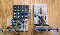
A working prototype I've now got a home-brew Arduino clone reading the keyboard and sending key-presses to a micro:bit using I2C. Preparing the Arduino clone was trickier than usual. As I mentioned in yesterday's post , the Arduino needs to run at 3.3 volts. That's the working voltage (V cc ) for the micro:bit, the Pi and the Jetson Nano. Connecting I2C lines from a 5v device would damage them, so 3.3 v operation is essential. I have a good stock of ATmega328P chips left over from the days when I was running Shrimping workshops. The ATmega328P  works well at 3.3 volts, so long as the clock frequency is no more than 8 MHz . Most Arduinos run at 5v with a clock speed of 16 MHz, so there's work to do.   8 MHz clock issues If I2C is to work reliably at 8 MHz the Arduino needs to be configured for an 8 MHz clock, and it needs a bootloader that works at that clock rate. My first step was to wire up a working clone on a breadboard with an 8 MHz crystal and i...

Adding a DS1307 Real Time Clock to Raspberry Pi

Image
Grove RTC The DS1307 RTC (Real Time Clock) is widely available, but adding one to a Raspberry Pi turned out to be a bit of a Yak shave. I'm gradually adding code and wiring instructions to my babelboard hardware and software projects, and I thought it was time to cover an RTC. I had a Grove RTC board from years ago and decided I'd document connecting that to a Raspberry Pi. The need for Battery Power First Yak Shave moment: RTCs normally use a coin battery to maintain power so they can keep time when their host is off, and the battery in my Grove board was way past its use-by date. This happened on Sunday evening, and the local supermarkets were shut, but the local convenience store was open. No CR1220, though, so I had to wait until the next day to get started. While I was waiting I read the data sheet for the DS1307 chip and realised I had another problem. Don't connect this chip directly to your Pi! Seeed Studios describe the DS1307 breakout as P...

I2C and SPI on the micro:bit; additions to the babelboard range

Image
micro:bit Keypad using I2C+ MC23008 For some reason there's not a lot on the web about using I2C and SPI with the BBC micro:bit. The I2C and SPI protocols allow single board computers like the micro:bit, the Raspberry Pi and Jetson Nano to drive hundreds of different types of useful peripheral chips. There are lots of widely available drivers for the Raspberry Pi, the Arduino and  Adafruit boards. I've seen fewer for the micro:bit, and I have started writing some more as part of my babelboard project . I am also building a babelboard for the micro:bit. The babelboard project Babelboards allow you to connect a range of I2C and SPI devices to several popular single board computers. The image on the right shows an mcp23S08 reading a hex keypad driven by a micro:bit using SPI. The micro:bit babelboard allows you to connect Grove I2C devices and the Quick2Wire port expander and analog boards. You can get adapters that connect Grove to Qwiik , so you can also con...

Raspberry Pi and BBC micro:bit for C2Pi

Image
Right now the Raspberry Pi and the BBC micro:bit look like a winning team. If you're f ollowing this blog you will know that I am evaluating new hardware and software for C2Pi (the re-generated C3Pi, neé Trackbot). Over the weekend I discovered that the micro:bit now supports MicroPython. Since I am looking for a micro that supports a language with a REPL, I had to investigate. MicroPython on the pyboard I've been a fan of MicroPython for a while. It runs on several platforms, including a custom board (the pyboard). I first met the pyboard, and Damien George, (its designer, and the original implementer of MicroPython) at an Open Technology conference in Cambridge a couple of years ago. I learned that MicroPython is a full, optimised implementation of Python 3; the only difference lies in MicroPython's specialised libraries, which  focus on direct access to the hardware. At the time I felt that the pyboard and MicroPython had great potential but I couldn...

Raspberry Pi Model B+ version detection

Image
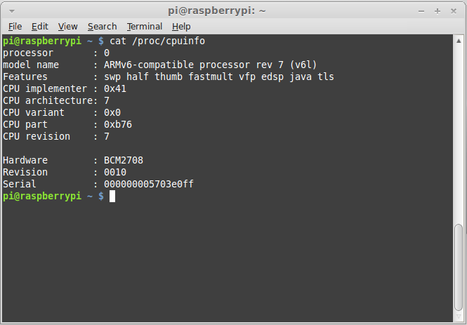
First, the good news. Existing code that relies on my revision detector script will work with Raspberry Pi Model B+. I'd forgotten how hacky my version detection code was. It assumes that if a board isn't revision 1, it must be revision 2. Here's the contents of /proc/cpuinfo for the new boards >> So the current detector thinks that boards are rev 2, and existing code will work because the layout for the first 26 pins on the Raspberry Pi header has not changed. What the current code won't do is let you know that you've got an extra 14 pins to play with. Fixing this requires two sorts of change: one to the detector (which is easy) and one to whatever code is using it. I'll take a look later in the week at what work will be needed to get the Quick2Wire GPIO code to give access to the extra pins, but before that I will check that current I2C code works OK. That too will need a (trivial) change to work correctly with a version of the detector th...

Raspberry Pi Model B+ first impressions

Image
and a worry! Farnell element14 have just delivered my new Raspberry Pi Model B+, along with some 40-way connectors. The Pi is destined for C3Pi , my Pi+ Arduino tracked robot. The main benefits of the Raspberry Pi B+ for C3Pi are the extra USB sockets and the reduced power consumption. I can see all sorts of possibilities created by the 40-way extended GPIO header, but I don't expect to take advantage of those in C3Pi. Unboxing the Raspberry Pi model B+ Raspberry Pi Model B+ Here is the Pi model B+. It's familiar, yet subtly different from its predecessors. It has a neater look about it and the 2x20 rows of GPIO pins are clearly ready for some serious work. I have one big question, which I hope to answer shortly: what is the hardware revision of the new board? Will some Python libraries crash on the Model B+? The board revision matters more than you might think. Back in the days when I was running Quick2Wire I came up with a little Python script you cou...

The Intelligent Breadboard project gets under way

Image
I've made a start on a project that I have had in mind for years - the Intelligent Breadboard, or TIB for short. TIB will look like a conventional breadboard, but its sockets will be connected to a set of port expanders. These in turn will be controlled by a microcontroller. You build your prototype on the breadboard in the usual way, and without applying power to your prototype, you'll instruct the microcontroller to check what is connected to what. If that matches what you expected, you'll apply power and check once again that the voltages are as expected. If you used Fritzing to design your breadboard layout, you'll be able to verify that the netlist from Fritzing matches the connections on the board. TIB will eliminate (or at least instantly detect) a lot of common breadboarding errors: missing connections, extra connections, wrong connections and loose connections. I expect it to speed up my prototyping significantly. Arduino + port expander The early...

lobstar and 7 segment I2C display - part 1

Image
One of the last projects that Quick2Wire worked on before the company ceased trading was a display based on the nxp SAA1064 controller and a 7-segment display. There's still a stock of the Quick2Wire boards over at SK Pang , but Quick2Wire never finished the 7-segment design. I'm thinking of restarting that project and I spent a little time this afternoon looking at what would be involved. It seems that the DIP version of the controller is no longer manufactured, and the only display I could find in my parts box is also no longer made. I don't think either of those issues is insurmountable; there seem to be a lot of the DIP chips for sale on eBay, and I guessed that the display pinout was probably the same as you find in more up-to-date displays from the same manufacturer. I was fairly sure that the display was a common-anode type, which the controller requires; I quickly lashed up a test circuit using a lobstar and checked the connections. lobstar and 7 segment d...

Text LCDs and the Raspberry Pi

One project I'm hoping to complete in the next day or so is an I2C-based Text LCD for use with the Raspberry Pi. Why bother? After all, the Pi has an HDMI output, and it's easy to connect the Pi via Ethernet or wireless. The problem is that there are situations where you really need a stand-alone display. Stand-alone Pi Projects If you're building a battery-powered  stand alone project you may need an output mechanism that's a bit more informative that a few flashing LEDs,  your power budget may not run to WiFi, and you may want to use what you're making in an environment where a network-based solution is not practical. Another application: running a physical computing course It may be hard to connect to the Pi because you don't know its IP address. Earlier this year I helped to run a couple of workshops covering physical computing on the Pi. Practical considerations meant that we couldn't use monitors for each Pi, and we had to connect to the lo...

A lesson from the mbed

Image
Yesterday in a short post about I2C  I published a fragment of code for the mbed. I wondered at the time why I was posting here rather than on the very helpful mbed site. Here's why. Take a look at the code, and think about the library it's using. The mbed I2C library is about as simple as you could wish for, but it does everything you need. You can even specify the I2C data rate at run time. On other platforms that small change is a big deal; Arduino requires you to recompile the Wire library, and the BeagleBone requires you to recompile  the kernel. The mbed library for SPI is just as good as its I2C library: simple, intuitive and complete . That's what we need on the BeagleBone and Raspberry Pi . We've been waiting for userland SPI support on the BeagleBone for a while, and we seem to be getting a mixed message from the kernel developers: It's really hard to do SPI right, and it will take a while It's done already; all you have to do...

BeagleBone driving LED Bar via I2C

Image
I've just posted a video of the BeagleBone driving a bar LED via I2C. The Bone is programmed in Python, and I'll shortly be checking the (open source) code in at Quick2Wire's github repository. Expect to see a Raspberry Pi performing the same trick as soon as we can get our hands on one! I hit a couple of snags while getting this going. Fortunately the inexpensive OpenWorkbench Logic Sniffer makes it really easy to debug I2C and SPI applications. I2C debugging with OLS: SCL is blue, SDA is green

Basics of I2C™

Image
The I2C bus allows you to connect several peripherals to one or more master controllers. In this diagram the controller is an Arduino; it is connected to a port extender and an LCD display. One commonly used port extender can drive up to 8 i/o lines; you might use four lines to control LEDs, and four lines to read push-buttons. It's a simple IC chip which costs about £1. All you do is connect it to ground, to a 5 volt power source and to the two data lines that form the I2C bus. The Arduino has a Wire library which allows you to turn the output lines on or off, and to read the state of the input lines. A commercial I2C LCD display is a bit more expensive (about £30). I built my own using a cheap serial LCD module (about £7) wired up to a port extender. I drive it using a modified Arduino library which someone else wrote for a slightly different port extender chip. The Arduino supports the original version of the I2C protocol which allows me to connect up to 127 different devices t...