Pages

Monday, 17 April 2017

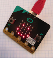
Resistomatic - an Arduino-based autoranging ohm-meter

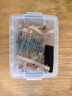
Sorting resistors is a pain


If you've been having fun with electronics for a while you've probably got a box
with bits in. I've been playing with electronics for six decades and I have lots of boxes, many of them containing random collections of resistors.

Resistors are cheap, but I hate waste, so from time to time I decide to empty some of the boxes and put the resistors away in their proper homes.

It ought to be easy, but it's a pain. I was never good at reading colour codes, and the problem has got worse with age. What I want is a simple, quick autoranging ohm-meter that I can use to measure resistor values.

So I'm making resistomatic.

Resistomatic requirements

Most of the resistors I use are 1% or 5% tolerance metal film resistors in the range 220 Ohms to 100K Ohms. Almost all the values  are in the E12 range.
(E12 values are multiples of 1.0, 1.2, 1.5, 1.8, 2.2, 2.7, 3.3, 3.9, 4.7, 5.6, 6.8, 8.2).

I'll be happy if resistomatic can achieve 5% accuracy over the range 220 Ohms to 100K Ohms. That should allow me to identify the resistors well enough, given that I will have samples of the value and its neighbours to compare it with.

Speed of measurement is not a big issue. If it takes a second or so for resistomatic to measure a resistor, that will be fine.

I don't want to spend a lot of time on the project, and I will only be using resistomatic occasionally. I've an unused Arduino Protoshield sitting in my stripboard box, so I will use that and plug it into an Arduino Uno whenever I need to make a resistance measurement.

My desktop computer has the Arduino IDE installed, so I will upload the Arduino sketch when I need it and view text output in the IDE's serial window.

A simple auto-ranging ohm-meter design using Arduino

A few years back I lashed up a simple version of resistomatic using a very simple approach.

One easy way to measure an unknown resistance is to use a voltage divider. You apply a known voltage across two series resistors, one known, one unknown, and measure the voltage at the junction. (As you'll see later, you'll need to use a number of different known resistors, but for now consider the simple case.)

If you ignore the current flowing through the voltmeter, Ohm's law says that I (the current flowing through the circuit) is 5/(R1+R2).

V (the Voltage across R2) is IR2 or R2*5/(R1+R2).

You know R1, you've measured V, and it's not hard to solve the equation for R2.

V =  5*R2/(R1+R2), so
V*R1 + V*R2 = 5*R2 hence
V*R1 = (5-V)*R2

Rearranging, we have
R2 = V*R1/(5-V) or
R2 = R1/(5/V -1)

Now you can calculate the value of the unknown resistance.

In an ideal world that calculation would be exact, but in reality there are several sources of error.

  1. The  value of R1 will not be exactly known.
  2. The applied voltage will not be exactly 5 volts.
  3. The Voltmeter's input impedance will be finite, so some current will flow through it.
  4. The Voltmeter itself will introduce some measurement error.

If you use the Arduino's 5v output the applied voltage should be accurate to within about 1%. You can use a 1% tolerance resistor for R1. The remaining errors relate to the Voltmeter.

Using an Op-Amp to increase accuracy


Boxes. Yay!
You can use a unity gain operational amplifier to buffer the input from the voltage divider. A unity-gain op-amp has an output that closely follows its input, but it has a high input impedance and a low output impedance.

An op-amp like the Microchip MCP6273 will divert very little current from the voltage divider. The MCP6273 available in an 8-pin DIP package, can run off a 5V supply, and costs about £0.60. Its output can vary over the full range of 0v to 5v. It's ideal for this application, and I had some in my OpAmp box. (You may have guessed by now I have lots and lots of boxes).

With an op-amp buffer the divider circuit now looks like this:


What value of R1 should you use? It turns out that you will get the best accuracy if the value of R1 is close to the value of R2, the resistance you are trying to measure.

Inexpensive commercial test-meters use a rotary switch to select the range used to measure an unknown resistance. You can do better by using the Arduino to connect each of a range of resistors, one at a time, and selecting the calculated value that corresponds to a measured voltage that's closest to 2.5 v.

How can you get the Arduino to connect each resistor in turn? You'll find a range of designs on the web, but one simple one works very well.

If you set one of the Arduino's digital pins to be an input, it has a very high impedance. So you connect a range of known resistors to several of the Arduino's digital pins, set all but one to be inputs, and one to be an output, and set that output high.

You've now applied 5 volts to one end of one resistor, and the other resistors are effectively disconnected.

If you connect the other ends of each known resistor together and connect the unknown resistor between  the common connection and ground, you have a voltage divider like the one described above.

Here's a Fritzing diagram.


The resistors on the right of the diagram are the alternatives for R1. After a bit of experimentation I settled on a range of values from 1K to 10M.

The sketch (Arduino code) to drive resistomatic is fairly simple.

/*
  Resistomatic

  Measures an unknown resistance using a voltage divider.
  Known resistors are attached to digital pins d7-d12
  Their other ends are commoned and connected to one end of the resistor under test.
  The other end of the resistor under test is grounded.

  setup opens the serial port and makes each of d7-d11 an input (so high impedence):
  loop:
     for each of d7-d11:
        make the pin an output
        set the output high
        wait 5 ms for the converter to settle
        read, convert and print the analogue reading
        make the pin an input
     wait 1000 ms


 */


const int analogInPin = A4;  // Analog input
const int PIN_COUNT = 8;
const int SAMPLE_COUNT = 10;

const int pin[PIN_COUNT] = {4, 5, 6, 7, 8, 9, 10, 11};
const float r1[PIN_COUNT] = {1000.0, 3300.0, 10000.0, 33000.0, 100000.0, 330000.0, 1000000.0, 10000000.0};


void setup() {
  // initialize serial communications at 9600 bps:
  Serial.begin(9600);
  // send all the pins we'll use low, and then configure them as inputs
  for (int i=0; i<PIN_COUNT; i++) {
     pinMode(pin[i], OUTPUT);
     digitalWrite(pin[i],LOW);
     pinMode(pin[i], INPUT);
  }
}

// take SAMPLE_COUNT succesive readings of the voltage and average them
float averageVoltage() {
  float total = 0.0;
  for (int i=0;i<SAMPLE_COUNT;i++) {
    delay(5);
    total += float(analogRead(analogInPin));
  }
  // convert to voltage and average
  return 5.0*total/(SAMPLE_COUNT*1023.0);
}

// see blog post for details of this caluclation
float calculateResistance(float r, float v) {
   return r/(5.0/v-1.0);
}

void loop() {
   float minimum = 2.5;
   float resistance = 100000000.0; // default value

   /* loop through finding the best estimate
      which we'll get when the measured voltage is closest
      to 2.5v  */
   for (int i=0; i<PIN_COUNT; i++) {
     pinMode(pin[i], OUTPUT);
     digitalWrite(pin[i],HIGH);
     float v = averageVoltage();
     digitalWrite(pin[i],LOW);
     pinMode(pin[i], INPUT);
     float difference = abs(v-2.5);
     if (5.0 > v && difference < minimum) {
        minimum = difference;
        resistance = calculateResistance(r1[i], v);
     }
   } 
   Serial.print("resistance = ");
   Serial.println(resistance);
   delay(3000);
} 

Update


I've transferred the breadboarded version to the Arduino shield. It works well, and will be really useful when I sort out my parts boxes. Here's the finished product:


Code and fritzing diagrams are on GitHub.

Wednesday, 5 April 2017

Program the Proto-Pic EDGE using O O MicroPython - part 1

Good programmers are Lazy.


According to Larry Wall (a very famous programmer) laziness is a virtue. Lazy programmers come up with labour-saving solutions.

If you’d like to save time for yourself and others by writing MicroPython code that’s easy to re-use, read on.

The article assumes that you are already familiar with the concepts of Object, Class and Composition, and that you know how to write a class definition in Python. If you’re not familiar with Object-Orientation (O O) in Python  you may find the code hard to follow. I’ve given a very brief introduction to O O later in this article.

There are several ways to learn about Python O O. There’s an ‘official’ tutorial here, but I’m not sure a beginner would find it easy to follow. There’s a whole book on the subject from Packt, and it looks good. It represents quite an investment in time and money, but I think it’s worthwhile if you are serious about improving your Python O O skills.

I will probably get round to writing my own introduction, but that’s a major project and will take a while. For now, even if you aren’t familiar with O O, you should be able to follow most of the article and run the example code
.
The O O application uses Proto-Pic’s new super micropixel EDGE add-on for the BBC micro:bit.

(Micro)Python is great for Physical Computing


Python is deservedly a very popular language for Physical Computing Applications.
Python is easy to learn, it’s expressive, and it’s freely available on Linux, Mac OS and Microsoft Windows.

Python gave the Raspberry Pi its name, and a lot of code published for the Pi is implemented in Python.

More recently, MicroPython has brought the language to several popular microcontroller platforms, including the BBC micro:bit.

But...


Most published Python/MicroPython scripts use a procedural style. That’s what most programmers start with, and it’s the style that’s most widely used in tutorials.

When programming in a procedural style you work out what you want the  computer to do, step by step, and your program is a procedure which specifies those steps.

It’s worth exploring other styles, and in this article you’ll see how to develop a simple Python application that makes some use of an O O (Object Oriented) style. In an Object Oriented program you program by creating objects - little packages combining data and code which can carry out simple tasks. The objects collaborate (interact with each other) in order to carry out more complex tasks. You specify the sort of objects your program needs by writing the definitions of classes which specify what a particular type of object knows (data) and what it can do (methods).

You can see the application running here:


The idea is simple. The application displays the current value of a counter using the micro:bit’s build-in display, and you can change that value up and down by using the buttons. Later on you’ll see how this simple idea could be adapted for use in practical projects.

You could implement the demo with a short script, but the script’s constituent parts would not be easy to use in other applications.

Here are a few variations that you might want to implement without having to start from scratch:

  • A display that shows a value using a bar LED display.
  • A display that shows the current light level or temperature.
  • A clock-style display that goes to 0 when the value goes up from 9.
  • A similar display that uses a different type of LED.
  • A display that shows the value by turning on just one LED at a time.
  • A display that shows different values in different colours.

Of course you could do that by creating multiple variants of your original script, but think what would happen if you found a bug in the original script. You’d have to make the same change in every copy!

That’s one reason why experienced programmers try to avoid duplicate copies of code. There’s even an acronym to help you remember: DRY, which stands for “Don’t repeat yourself”.

There’s another good reason to write your code by composing from simple components. Each component will be easy to test on its own. That can help you make to avoid bugs, and to track down and remove any that do creep into your code.

Let’s start to code.


You’ll need code which watches the buttons and tells the counter in your application to count up or down whenever one of the buttons is pressed.

There’s no need to use a class for that.

The application code creates and ‘wires together’ Counter and SimpleDisplay instances so as to achieve the desired result.

max_count = 10
disp = SimpleDisplayer()
counter = Counter(disp, max_count)
while True:
   if button_a.is_pressed():
       counter.up()
   if button_b.is_pressed():
         counter.down()
   sleep(200)

The last part should be self-explanatory.

 The code before it creates a SimpleDisplayer and a Counter. Let's start with the Counter. 


The Counter class

In this application a counter is a simple object which knows its current count, and can count up and down between its initial value of zero and some maximum value. In our case that maximum is 10.

The counter knows about another object which is notified whenever the counter’s value changes. Initially that will be a SimpleDisplayer object which will display the new value on the micro:bit's LEDs.

Here’s the code for the Counter class:

class Counter():
  # count ranges from 0 to max.
  # when the count changes disp (the displayer) is notified
  def __init__(self, disp, max):
      self._disp = disp
      self._max = max
      self._count = 0

  def update(self):
      self._disp.value(self._count)

  def up(self):
      if self._count < self._max:
          self._count += 1
          self.update()

  def down(self):
      if self._count > 0:
          self._count -= 1
          self.update()

The counter sends messages to a displayer.
Here is the code for a SimpleDisplayer which shows a value using the built-in LEDs:

# SimpleDisplayer shows the latest value on the micro:bit's LEDs
class SimpleDisplayer():
      def value(self, num):
          display.show(str(num))  

OOP makes for easy changes

This approach makes it very easy to adapt our application with a minor code change. Suppose that you want to display the current state of the counter using an array of LEDs like those available on the Proto-pic EDGE.

Here's the new version running:


Here’s the code which will drive the revised application:

from microbit import *
import neopixel

...

max_count = 10
leds = neopixel.NeoPixel(pin0, max_count)
disp = BarGraph(leds, BarGraph.YELLOW)
counter = Counter(disp, max_count)
while True:
   if button_a.is_pressed():
       counter.up()
   if button_b.is_pressed():
       counter.down()
   sleep(200)


The last part is unchanged.

The code before it uses two new classes: NeoPixel and BarGraph.

The Neopixel class is part of the micro:bit MicroPython distribution, so we just need to import the neopixel module to use it.

The BarGraph class is the new part of our application; we’ll need to write its definition and insert the code in the listing above.

Here’s the code for the BarGraph class:

# BarGraph uses an array of Neopixels or other similar LEDs
# to show the latest value
class BarGraph():
    # colo(u)r constants.
    # we use low values so the we don't strain the micro:bit's power supply
    WHITE  = (50,50,50)
    RED    = (50,0,0)
    BLUE   = (0,0,50)
    GREEN  = (0,50,0)
    YELLOW = (100,50,0)
    CLEAR  = (0,0,0)
    def __init__(self, leds, on_colour=WHITE):
        self._leds = leds
        self._count = len(leds)
        self._on_colour = on_colour

    def value(self, num):
        for i in range(self._count):
           if i < num:
               self._leds[i] = self._on_colour
           else:
               self._leds[i] = self.CLEAR
           self._leds.show()

The application code (shown earlier) creates and ‘wires together’ the Counter and BarGraph instances so as to achieve the desired result.

Modular code is much easier to change. In the next part of this two-part article we’ll look at changing the input to a light-sensing LDR and adding more colour to the BarGraph display.

We’ll also look at another major benefit of this approach: ease of testing.