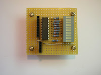
I'm making good progress on my MicroWriter clone. I decided to start by building Mk 2 of my Veroduino.
Mk 2 is more compact, and the green LED is connected to pin 13 by a jumper; one of my keyboard circuits needed to use pin 13 as an input, and the LED would have interfered with proper operation.
Mk 2 uses as resonator rather than a crystal; it also corrects a defect in the Mk 1 design, which tied the analog reference voltage pin (Aref) to Vcc. Aref is not normally connected; if it is, it should linked to ground by a small capacitor, but that's only recommended if you are doing very precise analog measurements.
I've corrected the schematic.
Thursday, 27 May 2010
Friday, 21 May 2010
Microwriter revisited
I'm taking a break from Test Equipment, and resuming a project that has been on hold for a couple of years.
It's a home brewed compact one-hand chorded keyboard inspired by the Microwriter.
I started the project using an Atmel ATMega8 hosted on SimmStick hardware. My tools for software development were primitive. WinAVR was still in its infancy, so like most Atmel developers I used AVR Studio and programmed in assembler or programmed in BASIC using Bascom from MCS Electronics.
I decided to use I2C to connect the micro controller to the keypad and LCD display. Driving I2C in assembler was a pain, and writing the keyboard handling in Basic was positively soul-destroying. I decided to wait until technology had improved enough to make the project enjoyable.
Fast forward two years. The Arduino offers an affordable hardware platform and an easy-to-use IDE. The main challenge is the keyboard itself; I'm going to experiment with QTC pills which look perfect for this sort of application.
Once I've put together a prototype keyboard I can drive it using an I2C board, an Arduino and an I2C LCD display. I'll use the I2C data logger to hold text.
Thursday, 20 May 2010
Arduino I2C Data Logging Board
I'm making great progress with my family of I2C™-based Test Equipment.
This data logger is one of the smallest, cheapest and simplest boards so far. It uses a 247C256 eeprom memory which has an I2C interface. This gives 32k bytes of external memory. The chip is widely available for £1 or so.
This picture includes a five-pence piece to give some impression of the scale.
If you're logging something like sunlight or wind speed, 32k bytes allows you to log an 8-bit value every minute for over 22 days.
A small design change would add more memory; the chip has eight possible addresses, so a board can contain eight of these chips, storing a total of 256k bytes. Other chips offer even greater memory capacity.
The back of the strip board has just 3 breaks, with pins 1-4 of the chip strapped to ground. That sets the configurable part of the chip's I2C address to 0.
You can drive the board with the Arduino's Wire library, and there is a sketch using this chip in the Arduino playground.
Tuesday, 18 May 2010
Arduino as an ISP
Yesterday, while experimenting with my Veroduino board, I managed to destroy its boot loader. Annoying, but not a show-stopper; I'd recently built the USBTinyISP from Adafruit, and felt sure I could quickly restore the corrupt boot loader.
I attached my USBTiny to my Windows laptop. It runs Windows 7, which refuses to load unsigned drivers without some fairly vigorous persuasion. Even when persuaded, it would not load the driver for the USBTiny. I think the driver may not not compatible with my laptop's 64-bit AMD processor. After an hour of unsuccessful experimentation I decided to try something else.
My next two attempts also failed. I can drive the USBTiny using avrdude on one of my Linux servers, but I can't install the latest Arduino IDE on that machine. The server is is running Ubuntu Hardy Heron, and I can't upgrade it easily. Its main job is to act as VMware host to a bevy of virtual servers, and VMware server currently needs patching before it will run on Karmic. I'd have to coax avrdude into some tricky fuse setting; it's easy to brick a chip if you get that wrong. I decided not to try.
Next I tried to use one of the virtual servers. It's running Ubuntu Karmic, and the Arduino IDE installs and runs, but it won't recognise the USBTiny. I suspect VMWare's virtual USB drivers are getting in the way.
Revenge of Windows 7
Not that simple, alas.I attached my USBTiny to my Windows laptop. It runs Windows 7, which refuses to load unsigned drivers without some fairly vigorous persuasion. Even when persuaded, it would not load the driver for the USBTiny. I think the driver may not not compatible with my laptop's 64-bit AMD processor. After an hour of unsuccessful experimentation I decided to try something else.
My next two attempts also failed. I can drive the USBTiny using avrdude on one of my Linux servers, but I can't install the latest Arduino IDE on that machine. The server is is running Ubuntu Hardy Heron, and I can't upgrade it easily. Its main job is to act as VMware host to a bevy of virtual servers, and VMware server currently needs patching before it will run on Karmic. I'd have to coax avrdude into some tricky fuse setting; it's easy to brick a chip if you get that wrong. I decided not to try.
Next I tried to use one of the virtual servers. It's running Ubuntu Karmic, and the Arduino IDE installs and runs, but it won't recognise the USBTiny. I suspect VMWare's virtual USB drivers are getting in the way.
Arduino to the rescue
Then I came across an article on the main Arduino website which explained how to use the Arduino as an ISP. It took about five minutes to wire the Arduino up to my Veroduino clone, and a minute later the Veroduino had a working boot loader again. Even better, I can use the same approach to program other Atmel chips, including my stock of ATMega8s.Arduino DVM with LCD Display
A Digital Voltmeter (DVM) is one of the first things you need if you're building electronics projects. Most of us have one. But what if you need more than one?
Enter the Arduino. If you have an Arduino that can drive an LCD, you've got a multi-channel voltmeter!
The sketch uses my LCD I2C library; I'll publish that and the LCD board design in the next few days.
Enter the Arduino. If you have an Arduino that can drive an LCD, you've got a multi-channel voltmeter!
#include <lcdi2c.h>
#include <wire.h>
int ADDR = 0x21;
LCDI2C lcd = LCDI2C(ADDR);
float volts[4] = {0.0};
int pin;
void setup()
{
Wire.begin();
lcd.init();
lcd.print("4-ch Arduino DVM");
}
void loop()
{
lcd.cursorTo(2,0);
for (pin = 0; pin < 4; pin++) {
volts[pin] = (5.0 * analogRead(pin)) / 1023;
lcd.print(volts[pin], 1); lcd.print(" ");
delay(10);
}
}
The sketch above turns an Arduino with an I2C LCD display into a four-channel voltmeter. The Atmel ATMega328 on which the Arduino is based has six analog inputs but two of them are used by the chip's I2C support. That leaves four channels - plenty for most purposes.The sketch uses my LCD I2C library; I'll publish that and the LCD board design in the next few days.
Monday, 17 May 2010
An Excellent Eagle Course
I spent this Saturday at a free CadSoft Eagle course for Arduino users which had been organised by Tinker London and Farnell's Element14.
Over twenty of us crammed into a well-equipped course room at the Cavendish Conference Centre. The main presenter was Tinker's Peter Knight. Alexandra Deschamps-Sonsino (the CEO and co-founder of Tinker) explained that when she first asked Peter to run the course he said he could cover the subject in three weeks. Somehow he managed to cover the essentials in just a few hours!
Peter was supported by Lynn Ma, Mei Wang and Alistair Winning from Farnell, and by Richard Hammerl from CadSoft. Richard knows Eagle inside-out; he's an active member of the Eagle forum on Element14, so I know I'll get a fast and helpful response to any queries I have about using the software.
Everyone had done their homework and arrived with the latest version of Eagle on their laptops. In the morning Peter covered creating a schematic and laying out a PCB. After lunch we learned how to create new parts libraries and looked at preparing a board design for manufacture by a PCB Fab shop.
Finally Richard covered the licensing options which include a free licence for the lite edition for hobby use.
The course was aimed at advanced Arduino users who wanted to design their own add-on boards. The participants came from a wide range of backgrounds; artists, musicians, hobbyists and professional electronics engineers. Everyone I spoke to felt they'd got a lot out of the day.
Farnell and CadSoft are clearly committed to the development of Eagle and its user community. I finished the course confident about how to use Eagle, motivated, eager to learn more and to play an active role in the online Element14 community.
Thanks to Tinker for an excellent workshop (and allowing me to use their flickr photo) and to Farnell and CadSoft for the support that made the course possible.
I2C LCD board
In the previous post I mentioned that most of the boards I'm working on use I2C™ port expanders. The latest is an LCD driver which uses a Phillips PCF8574 I2C 8-bit expander to drive a 2x16 character LCD. The only Arduino pins used by the display are pins 27/28; they can be used to drive other I2C boards as well.
The Arduino software to drive the LCD is very simple. Here's the code used for the picture above:
#include <:lcdi2c.h>
#include <wire.h>
int ADDR = 0x21;
LCDI2C lcd = LCDI2C(ADDR);
void setup()
{
Wire.begin();
lcd.init();
lcd.print("test");
}
void loop()
{
lcd.cursorTo(2,0);
lcd.print("time:");
lcd.cursorTo(2,6);
// print the number of seconds since reset:
lcd.print(millis()/1000);
}
Simple LED Bar Logic Tester
What happens when you power-up your latest electronic creation for the first time?
Sometimes it just works, but for most of us that's the exception rather than the rule. If your circuit isn't working as expected, how do you track down the problem?
I've been using this LED Bar Logic tester to debug some of my Arduino™ add-ons. It's very simple - a row of sockets connects to a ULN2803A, which drives 8 of the LEDs in a 10-LED bar display. The ninth LED is unused; I use the tenth to indicate if the 5v supply is on.
Most of the boards I'm working on at the moment are driven by an I2C™ port expander. I use the LED bar tester to check that the state of the port expander outputs is what I expect. Of course you can also use it to check the status of the Arduino pins.
Here's the schematic. SCL and SDA are usused; they are part of the I2C bus which runs along the bottom of all my test boards.
Sunday, 9 May 2010
Fritzing is fun!
An Electronic CAD program I can live with
and it's free!
Readers will know that I'm sceptical about Electronics CAD software. Most of what I've tried seems counter-intuitive, and the open source pacakges have either been buggy or hard to install.A couple of days ago I discovered Fritzing, and I'm really enthusiastic. Fritzing is alpha software, but it's very usable - indeed, Adafruit (one of the best-known names in the Open Source Hardware space) have been using it for months.
Here are the features I like the most:
You start by creating a virtual breadboard of your project.
Here's a sample of the breadboard view for an Arduino-based hardware 'Hello World' ( a flashing led circuit).
You create it by dragging components from a bin and placing them on your work surface.
When you drop a component on the breadboard it's automatically plugged in.
You can select wires and drag them to the things they connect to.
I find the interface is very natural.
Here's a photo of the real-life version for comparison.
The virtual breadboard is realistic enough that just about anyone could set up the real breaboard by using it - pretty valuable if you are creating a course!
It's easy to draw schematics.
Once you've got your breadboard laid out, just switch to schematic view. Tidy up and export.
Most popular formats are available, including pdf, jpg, png and svg.

Just switch to the PCB view, autoroute, and export.
You can export images (like this one) or you can create gerber files ready to send off to a PCB Fab shop.
Simple!
It's (fairly) easy to add new components.
Components are defined by an xml file. This file references three svg files which define the Breadboard view, the Schematic view and the PCB view. You can create the svg with tools like Inkscape or Illustrator. I'll be using my Python library to do most of the work and use Inkscape for last-minute edits.
You can upload new components to the Fritzing website so that others can use them.
As you'd expect from alpha software, Fritzing has some limitations. In particular it will only lay out single sided boards at present, but that will be sufficient for many hobbyist users.
It feels robust, it's ituitive, it has a lively and helpful user community and the price is right!
Saturday, 8 May 2010
Arduino on a budget - part 7
The Mk 1 is a little fiddly to construct; I hope to build Mk 2 as soon as the components arrive.
The two strips alongside the microprocessor (MPU) allow you to link plugboard components to any MPU pin.
The male jumper to the left of the MPU allows you to provide power from a FTDI USB TTL cable, and to program the device using the Arduino development environment.
The pushbutton resets the MPU; you need do a manual reset while programming. Timing the reset is a matter of trial and error. I will buy and build a USB breakout board soon. That should perform an auto-reset when programming.

Four of the breaks are underneath the jumper for the FTDI cable. The outside jumper pins are soldered to stipboard tracks; the rest of the used pins are soldered to three wires which come down from the top side of the board through three small holes.
One pin has been removed from the jumper, as that signal (CTS# on the FTDI cable) is not used.
The fifth break (on the bottom row of strips towards the right of the board) is there to support thegreen pin13 status LED. Both leds are 3v 3mm types with a built-in current limiting resistor from Maplin.
The board uses components from oomlout's Arduino Compatible Component Bundle. I got the board and spacers from Maplin. The spacers need M3 bolts to secure them to the board.
My design for the board borrows heavily from the work of others; for details see part 1. The schematic is in part 6.
Thursday, 6 May 2010
Developer shot by Arduino™!

I bought them both from S K Pang - a UK supplier who provided very quick delivery. They appear identical to the camera and trigger described on the SparkFun website.
Sadly, supplies of both components are likely to be limited. The manufacturer has replaced the camera with a higher-function model at a much higher price. The trigger is no longer offered on the S K Pang website and Sparkfun shows the camera as out-of-stock.
This is frustrating, as the combo are fairly inexpensive and easy to use. Picture quality is not what you'd get from a digital camera but it's good enough for robotics vision projects and for the boat security application that I'm currently working on.
The camera has a well-documented UART interface. When fired, the trigger board requests a jpeg image from the camera and records it on a microSD memory card.
The trigger board is driven by an Arduino-compatible Atmel atmega328 chip. You can solder a header to the board so you can reprogam it using an FTDI TTL USB cable. Sparkfun have provided the source, so it should be easy to extend the software.
Saturday, 1 May 2010
Arduino on a budget - 6
Subscribe to:
Posts (Atom)