Pages

Friday, 26 February 2021

More Raspberry Pi Pico experiments

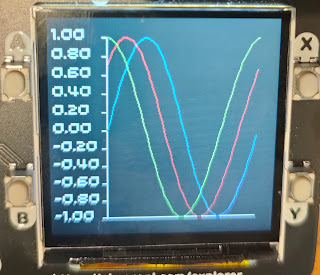
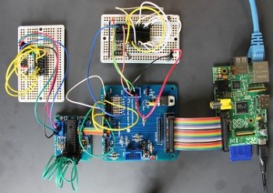
If you're exploring the Raspberry Pi pico, here are some more resources

MicroPlot

I've started a new project called MicroPlot. It's been developed on the Pico though it will eventually work on other  micro-controllers and computers. It's a minimal plotting package and it already has enough functionality to be useful.

It will plot simple line plots; the first example below is a series if sine waves and the second shows the voltage across a capacitor as it charges and discharges.

Plotting Sine waves

Capacitor charging and discharging


MicroPlot has its own project on GitHub. You can read about it and download the code at https://github.com/romilly/microplot and I will be soon be using it for some more electronics experiments.

Using the UART

The current MicroPython documenation for the Raspberry Pi Pico is a bit thin on detail about using the UART. I've added a short example in my pico-code project on GitHub.

The Tiny2040 is available from Pimoroni!

Pimoroni Tiny2040


I was lucky enough to get an early pre-production version of the Pimoroni Tiny2040.

It's now available in the Pimoroni shop.

You'll find a couple of simple examples in my pico-code project. They are in the
 src/pico_code/pico/tiny2040/ 
directory.

Resistomatic

Over the years I've blogged about a number of implementations of resistomatic, a home-made resistance meter. Most of them use an 8-bit ADC which complicates the design because 8 bits give a low resolution. The pico's ADCs are 12-bit. My crude design just needs a bridge that compares the voltages across the reustor to be measured and a know 1K ohm resistor. It's accurate enough (5%) for my purposes across a range of resistance. I've checked it with resistors ranging from 56R to 100K ohms.

You'll find the code and little more information at https://github.com/romilly/pico-code/blob/master/docs/resistomatic.md


More on the way

I've several more Pico projects in the pipeline. To stay up-to-date as I release them, follow @rareblog on twitter.


set up a new GitHub

Saturday, 13 February 2021

MicroPython development on the Raspberry Pi Pico

Get Started with MicroPython on Raspberry Pi Pico suggests that you use the Thonny editor for development.

Thonny will get you off to a quick start, but you may have an alternative editor you'd prefer to use.

Lots of my friends now use VS Code; some are vim or emacs experts; many, like me, use PyCharm as their normal Python development environment.

I find it more comfortable to use my normal editor for MicroPython development, but I have more compelling reasons.

The first is refactoring support. I'm learning as I go, and I often want to improve the design of my code libraries as I come to understand things better. PyCharm does a very good job of refactoring Python code.

There's another issue to do with version control.

I'm currently sharing my Pico code on GitHub. That means I need to keep code on the Pico in sync with the code on my workstation. I haven't found an easy way to do that with Thonny, so I am using another tool to move and test code.

rshell was my first choice, but I've had some problems with it, as have others.  Les Pounder (@biglesp) came to my rescue. He has a really useful series of blog posts called Tooling Tuesday.

A while ago Les recommended Adafruit's ampy for use with MicroPython boards. Ampy works really well with the Pico. I now have it on my workstation, and on a Raspberry Pi which I also use for Pico development.

Les also recommends tio for serial communications. tio is a serial terminal program. Its great advantage over others is that it will try to reconnect automatically if the serial link goes down. tio is available on the Pi but I couldn't find it in the official repositories for my very backdated Linux Mint installation. Fortunately it took just three minutes to download tio and build it from source, following the instructions on its GitHub page.

I'll soon be publishing more Pico and Tiny2040 code. If you want to stay up to date, follow me (@rareblog) on twitter.


Friday, 12 February 2021

Raspberry Pi Pico project 2 - MCP3008

This post show you how to drive the MCP3008 8-channel ADC using a Raspberry Pi Pico. I'll start with a personally embarrassing and annoyingly relevant story. I'll also tell you about a minor 'gotcha' when using SPI on the Pico, and how you can avoid it. Finally, I've include the code and fritzing diagram I used to test the interface.

First, the story.

Back in 2012, when the Raspberry Pi was fresh and new, I was running a startup called Quick2Wire.  We made add-on boards for the Pi. Just before Christmas we sent out our first batch of boards to a small army of beta-testers.

The beta boards didn't work.


Somehow a single trace on the pcb had got deleted and one of the GPIO pins was isolated. The boards were still usable and it wasn't too hard to solder in a jumper wire to replace the missing trace, but it was very embarrassing.

It wasn't just that we'd shipped boards with a defect. The really annoying thing was that I'd set up an  automated loop-back test harness, but in a fit of over-confidence I just did a quick manual test on the board before we sent them out.

The automated test would have caught the problem which my quick manual test failed to spot.

I'll come back to loop-back testing below.

Back to the Pico

One of my goals for my Pico mini-projects was to verify that I could drive I2C and SPI chips using the Pico's MicroPython. I2C and SPI protocols are really useful.They let you drive all kinds of interesting sensors and actuators, and that means that they enable lots and lots of interesting applications.

There are an SPI example in the excellent Getting Started guide, and it gave me some useful ideas. There's a little more information in the Pico Python SDK documentation, and yet more clues in the Pico pinout diagram. I also found a CircuitPython driver for the MCP3008 on Adafruit's GitHub repository.

I reckoned that I now had enough information to wire up and drive an MCP3008 chip. The MCP3008 is an 8-channel  ADC (analogue-to-digital) converter. The Pico has 3 ADC pins, but sometimes you need more. The 3008 has a simple, well documented SPI interface, and I had a few in my parts bin, so it was an obvious choice for the test.

I quickly wrote some code, and sure enough it worked. I posted it as a gist on GitHub and tweeted about it.

Some time later that day I got a comment from Matt Trentini, one of the members of  a Facebook group that covers the Pico and other MicroPython controllers. He suggested a small refactoring to the code. It clearly made the code better, and I decided to implement it.

Loopback tests

Some people are smart enough to be able to refactor code without tests but I am not one of them.

I decided to create a loop-back test. In a loop-back test the UUT (unit under test) provides an output which is connected to one of its inputs. In other words, the output is looped back  to the input. When you change the output, the input should change. If everything works as expected, the loop-back test passes.

In this case, I just connect a GPIO pin to one of the MCP3008 inputs. When the GPIO output is high the MCP3008 should read 3.3 volts; when it's low, the MCP3008 should read 0 volts.
I set up a loop-back test and ran it. It worked.

I did the refactoring and the test stopped working.

What had I done wrong?

SPI defaults on the PICO


The Pico has two hardware SPI busses, and you can access each buss from several different pins. An SPI chip needs three data inputs and one chip selection input. The data inputs are traditionally called SCK, MISO and MOSI. SCK carries a clock signal. MISO carries data from the chip to the Pico, and MSOI carries data from the Pico to the chip. Because the Pico can be a controller or be controlled by SPI,  the Pico's pinout diagram calls MISO  SPI RX and calls MOSI  SPI TX.

The Pinout diagram covers both SPI busses, and the example in the Getting Started book shows an example that uses Pin 2 as SCK, Pin 3 as TX and Pin 4 as RX.

I wrongly assumed that those were the default pins. In the first bit of code I specified the pins explicitly. In the refactored code, I used the default SPI constructor.

After hours of puzzlement I discovered from the Pico Python SDK documentation that the default pins are 6, 7 and 4, not 2, 3 and 4 as used in the book example. It was easier to change my code than to change my wiring, so the code on GitHub now specifies the pins explicitly.

Here's the code for the MCP3008 class.
"""
MicroPython Library for MCP3008 8-channel ADC with SPI

Datasheet for the MCP3008: https://www.microchip.com/datasheet/MCP3008

This code makes much use of Adafruit's CircuitPython code at
https://github.com/adafruit/Adafruit_CircuitPython_MCP3xxx
adapted for MicroPython.

Tested on the Raspberry Pi Pico.

Thanks, @Raspberry_Pi and @Adafruit, for all you've given us!
"""

import machine


class MCP3008:

    def __init__(self, spi, cs, ref_voltage=3.3):
        """
        Create MCP3008 instance

        Args:
            spi: configured SPI bus
            cs:  pin to use for chip select
            ref_voltage: r
        """
        self.cs = cs
        self.cs.value(1) # ncs on
        self._spi = spi
        self._out_buf = bytearray(3)
        self._out_buf[0] = 0x01
        self._in_buf = bytearray(3)
        self._ref_voltage = ref_voltage

    def reference_voltage(self) -> float:
        """Returns the MCP3xxx's reference voltage as a float."""
        return self._ref_voltage

    def read(self, pin, is_differential=False):
        """
        read a voltage or voltage difference using the MCP3008.

        Args:
            pin: the pin to use
            is_differential: if true, return the potential difference between two pins,


        Returns:
            voltage in range [0, 1023] where 1023 = VREF (3V3)

        """

        self.cs.value(0) # select
        self._out_buf[1] = ((not is_differential) << 7) | (pin << 4)
        self._spi.write_readinto(self._out_buf, self._in_buf)
        self.cs.value(1) # turn off
        return ((self._in_buf[1] & 0x03) << 8) | self._in_buf[2]

And here's the code for the loop-back test.
from machine import Pin, SPI
from time import sleep, sleep_ms
from mcp3008 import MCP3008

spi = SPI(0, sck=Pin(2),mosi=Pin(3),miso=Pin(4), baudrate=100000)
cs = Pin(22, Pin.OUT)
cs.value(1) # disable chip at start

square = Pin(21, Pin.OUT)

chip = MCP3008(spi, cs)

while True:
    square.value(1)
    actual = chip.read(0)
    print(actual)
    sleep(0.5)
    square.value(0)
    actual = chip.read(0)
    print(actual)
    sleep(0.5)

Finally, here's the fritzing diagram for the loopback wiring.


I've several more mini-projects to cover in the next day or so. If you want to keep track of what I'm up to, follow me (@rareblog) on twitter.


Raspberry Pi Pico - simple projects

Introducing fungen - an AF function generator.

Lots of pioneers are now creating tutorials and sample projects for the Raspberry Pi Pico and the Pimoroni Tiny2040.

One of my first mini-projects is fungen - a Pico-based AF (audio frequency) function generator that uses the Pico's PIO (programmable I/O) to generate a waveform.

The Pico's head start


The Pico was announced just a few days ago. It arrived out of the blue complete with lots of interesting add-ons available, and with excellent documentation.

The reference documentation is full of useful examples, including several that take advantage of the Pico's powerful PIO. PIO allows users to set up custom input-output capability, and one of the examples shows how to use PIO to implement PWM (Pulse width modulation).

The Pico already has plenty of PWM-capable pins, but I wondered if I could hack the PWM code to turn the Pico into a simple signal generator.

Indeed you can, and that's how fungen works.

I made a couple of minor changes to the  PIO PWM sample code and wrote a short program on my workstation that generated the values I needed to to generate a sine wave. Next I wired up a very simple low-pass fiter from a capacitor and resistor. I fired up my BitScope micro USB-based oscilloscope, loaded my code onto the Pico using the thonny editor, and took a look at the output.

It worked!


Of course a useful signal generator lets you vary the frequency of its output. That's usually done using a knob that turns a potentiometer. Could I use that with the Pico?

I worried that the reading of the voltage would interrupt the process of generating the sine wave. I quickly realised that the Pico has a multi-core. Could I use the second code to read the pot?

I couldn't find a micropython example of multi-threaded code for the Pico, but Ben Everard quickly came to my rescue. He's written some code that uses both cores, and it turns out to be really easy.


Multi-threading on the Pico


Here's the current code for  the function generator.
# Example of using PIO for function generation using hacked PWM example

from machine import ADC
from time import sleep_us, sleep_ms
import _thread

from pio_dac import PIOPWM

# Pin GP22 is output
pwm = PIOPWM(0, 22, max_count=250, count_freq=10_000_000)

sines = [
    124, 127, 130, 133, 136, 139, 142, 145, 148, 152,
    155, 158, 161, 164, 167, 170, 172, 175, 178, 181,
    184, 186, 189, 192, 194, 197, 200, 202, 204, 207,
    209, 211, 214, 216, 218, 220, 222, 224, 226, 227,
    229, 231, 232, 234, 235, 237, 238, 239, 240, 241,
    242, 243, 244, 245, 246, 246, 247, 247, 248, 248,
    248, 248, 249, 249, 248, 248, 248, 248, 247, 247,
    246, 246, 245, 244, 243, 242, 241, 240, 239, 238,
    237, 235, 234, 232, 231, 229, 227, 226, 224, 222,
    220, 218, 216, 214, 211, 209, 207, 204, 202, 200,
    197, 194, 192, 189, 186, 184, 181, 178, 175, 172,
    170, 167, 164, 161, 158, 155, 152, 148, 145, 142,
    139, 136, 133, 130, 127, 124, 120, 117, 114, 111,
    108, 105, 102, 99, 95, 92, 89, 86, 83, 80,
    77, 75, 72, 69, 66, 63, 61, 58, 55, 53,
    50, 48, 45, 43, 40, 38, 36, 33, 31, 29,
    27, 25, 23, 21, 20, 18, 16, 15, 13, 12,
    10, 9, 8, 7, 6, 5, 4, 3, 2, 1,
    1, 0, 0, -1, -1, -1, -1, -1, -1, -1,
    -1, -1, -1, 0, 0, 1, 1, 2, 3, 4,
    5, 6, 7, 8, 9, 10, 12, 13, 15, 16,
    18, 20, 21, 23, 25, 27, 29, 31, 33, 36,
    38, 40, 43, 45, 48, 50, 53, 55, 58, 61,
    63, 66, 69, 72, 75, 77, 80, 83, 86, 89,
    92, 95, 99, 102, 105, 108, 111, 114, 117, 120,
]


pot = ADC(26)
delay = [400]


def read_pot():
    while True:
        v = pot.read_u16()
        delay[0] = 20 + (400 * v)// 65000
        sleep_ms(100)


_thread.start_new_thread(read_pot, ())

while True:
    for i in range(0, 250, 25):
        pwm.set(sines[i])
        sleep_us(delay[0])

It uses pio-dac.py which is the hacked version of the PWM example. You'll find all the code (and some other examples) on GitHub.

I'll blog about more of the examples over the next few days. If you want to keep track of what I'm up to, follow me (@rareblog) on twitter.