Pages

Monday, 24 November 2014

C3Pi is innocent, Flora not so much, and more Shrrimps are on the way.

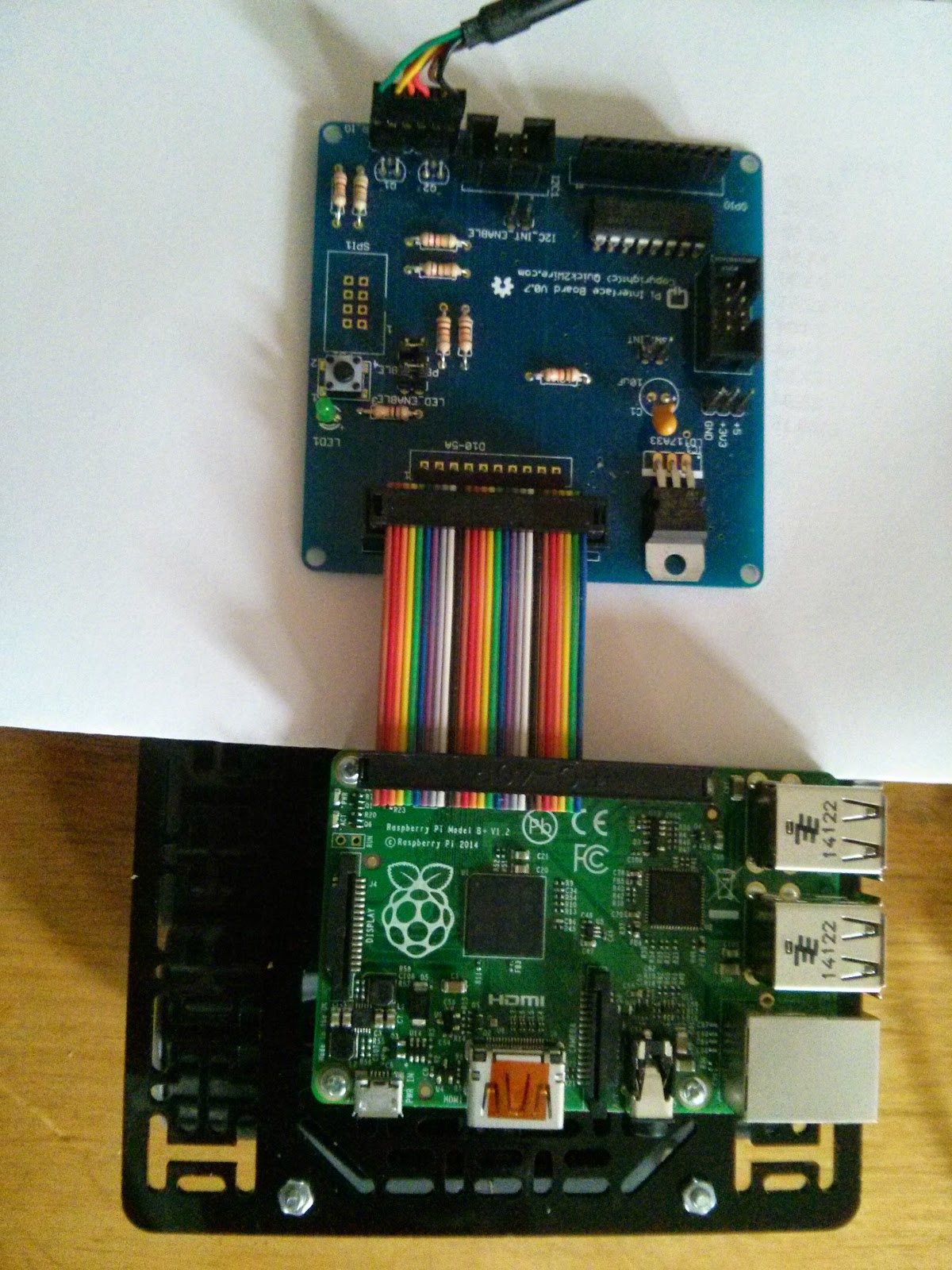
I took C3Pi to the Elephant and Castle Mini Maker Faire a few days ago, but had to leave early since he suddenly stopped working.

At the time I blamed a loss of battery power, and thought that he'd wiped the file system on his SD card. Various holdups meant that I have only just been able to try to fix the problem which turns out to be rather simpler.

C3Pi has two controllers on board: a Raspberry Pi model B+ does the thinking, and a Teensy 3.1 controls his motors. The Pi B+ uses a micro SD card but when I removed it the card was even more micro than usual: half the card had been broken off!

I have no idea how this happened but poor old C3PI is off the hook. He's now back in action with a newly-flashed SD card and will soon be getting the first of a series of upgrades.

I mentioned that I had only just been able to get around to investigating the problem. I spend several days after the Faire learning about wearable electronics. I'd been asked if I could help with a wearables workshop at last Saturday's Southend Raspberry Jam, and as I knew next to nothing about the Adafruit Flora or Gemma I got some hardware and started to tinker.

I run Linux on my workstation and laptop and I soon found that Linux is the poor relation when it comes to programming Gemma and Flora. I can program Gemma using my workstation, but the laptop does not see the device at all, and neither sees the Flora. Nonetheless I managed to get enough code working to feel prepared.

Alas, on the day I was very poorly and had to stay at home. My friends at Southend
seem to have forgiven me as we're now planning a Shrimping It! worksop in February. More details soon.

Thursday, 20 November 2014

Wearable electronics with Gemma and Flora

From Wembley to Southend

Adafruit Gemma
This evening I'm off to Createspace in Wembley to work on some wearable electronics. I'm helping with a wearable electronics workshop at this weekend's Southend Raspberry Jam, and I need to practice!

I've been to several Raspberry Jams at Southend, and thoroughly enjoyed them. There's always a strong local presence as well as a group of regular visitors from further away. Great talks and workshops - whether you're an beginner at making things or an old hand, you'll find interesting and helpful people.

Createspace

Createspace is my nearest maker space. I've been to the London Hackspace, which is awesome, but it takes me a while to get there from home. Createspace has an impressive collection of facilities and is much easier for me to get to. They have open nights, and there's a regular meetup for electronic hackers.

Gemma and Flora

Tonight I'll be experimenting with Adafruit's Gemma and Flora. Gemma is tiny; Flora is a little larger, but adds support for I2C. Both are supported by a specially configured version of the Arduino IDE which is available from the Adafruit Website.

My goal tonight is just to get familiar with the available libraries and get a simple proof-of-concept working. Once I feel comfortable I have a little project in mind. More details soon.

Advice, please!

I'm looking forward to helping at this Saturday's workshop but I'm a slightly nervous novice :)

If you have any tips or gotchas, do please tell me about them in a comment! I'd really appreciate it.


Saturday, 15 November 2014

C3Pi - Fun and Frustration at the Elephant and Castle

C3Pi from above

I went along this morning to the Elephant and Castle Mini Maker Faire to introduce C3Pi to some of my fellow makers.

The event was extremely well organised and I had no problem finding my desk and setting up. Before long C3Pi was running through his paces - fairly limited at the moment, as he still has no sensors and is controlled by a very simple command line interface.

That's about to change, thanks to Joe Walnes' brilliant websocketd - more details below.

In spite of his limited repertoire C3Pi soon made new friends and performed admirably. It's always a little nerve-wracking when he runs on a desktop. He has been known to get over-excited and career off in unexpected directions, but this morning he behaved himself...

Power problems

... until just before lunchtime, that is.

I'm still not certain what happened, but I think C3Pi's batteries ran low. What I know is that the ssh session connecting my laptop to the Pi suddenly started behaving strangely, and C3Pi's file system was completely corrupted.

There's quite a lot of work needed to recreate the file system and I had to take C3Pi home to repair the damage. Next time I'll prepare and take a backup SD card! I'll also trying out the Pi UPS which is designed to avoid just this sort of problem. By then C3Pi should aslo have a proper web interface.

A web interface using websocketd

I've wanted to provide a web interface to C3Pi for a while, but never got around to it. I am currently experimenting with a browser interface using websockets, based around Joe Walnes' websocketd interface.

websocketd makes it incredibly easy to web-socket enable any program that reads from standard input and/or writes to standard output.

There's an easy-to-follow example in the 10 second tutorial, with more detail in the 10 minute tutorial.

The software is really easy to install. It's a single, small stand-alone executable, with versions available for WIndows, OSX and Linux. The Linux versions include one for ARM processors and websocketd runs well on the Pi.

If you want a really simple way to control or observe stuff via a web browser, take a look at websocketd. Recommended.


Saturday, 27 September 2014

Pegasus Autocode Revisited

Pegasus, courtesy Wikipedia
Is this the longest-running debugging session of all time?

Back in 1958 I wrote a little program in Pegasus Autocode.

The Ferranti Pegasus was an early (and very successful) UK computer, and as an 11-year old I was lucky enough to borrow a manual and have my program run.

The kind person who ran my program fixed a couple of problems for me, but I've never been quite sure what they were.

Today I found out, and finally got to fix the program myself.

PEGEM to the rescue

I've known for a while about Chris Burton's wonderful PEGEM Pegasus Emulator. This is a DOS program which provides a pretty complete simulation of the Pegasus.

You control the program via the switches on the operator's console. The drum is loaded with the Initial Orders (the Pegasus Operating System), and you can create your own five-track punched paper tapes which you use to program the computer and provide data.

A missed excursion and a loose end tidied

Yesterday I had hoped to join a group of enthusiasts on a Computer Conservation Society outing to IBM Hursley Park, but a tummy bug meant that I was unable to travel.

I decided to install PEGEM on my workstation and have a nostalgic play with Pegasus.

I hadn't realised until yesterday that PEGEM's virtual storage cabinet of paper tapes included the master tape for Pegasus Autocode. This meant that I could try to recreate my program and run it again - after a lapse of over 50 years!

Calculating e

The program attempted to calculate the value of e using a power series. Pegasus Autocode had a perfectly good EXP function available, but back in 1958 I thought I would learn more by doing it the hard way.

I still have my own copy of the Autocode manual, so I decided to have another go.

I recreated the program (from memory) as a text file and converted it to paper tape format.
I managed to reproduce the original bug but this time I was able to fix it.

The problem was due to a well-documented restriction in the Autocode language. I'd attempted to mix floating-point and integer calculations in a  way that Autocode does not support; once I fixed that the program ran and printed out a reasonable approximation of e.

The working version - after 55 years

Here's the final working version. The format looks a bit strange, as the paper tape had its own specialised character set. The ^ is actually a right arrow, representing a jump (goto) in autocode, and the | is a figure shift character used as a spacer.

|||||||||||||||
D
N
CALCULATION OF E
||||||||||
J1.0

v1 = 1.0
v2 = 1.0
v3 = 0.00001
v4 = 1.0
1) ^2, v3 > v2
v2 = v2 / v4
v1 = v1 + v2
v4 = v4 + 1.0
^1
2) PRINT v1, 3026
STOP
(^0)
|||||||||||
@@@@@@@
||||||||

and the result when you run it is: +2.71828

Yay!


Wednesday, 13 August 2014

C3Pi: The Teensy and Motor Driver are talking

C3Pi Teensy 3.0 and Motor Driver
At the end of the previous post I let myself get a bit carried away!

C3Pi has always used a Solarbotics motor driver. In the past it's been controlled by an Arduino Pro Mini.

While the software for the Teensy is very similar, I needed to make a couple of changes to the code and more significant changes to the pinout.

Slow and steady

So my rush to solder up some stripbaord was premature. I've breadboarded the circuit instead.

I've now got the Teesny 3.0 controlling it, and the Teensy is controlled by serial input.

Since I've already checked that the Pi can drive the Teensy's serial port, I'm ready to go.

Tomorrow's plan

Tomorrow I will prepare the stripboard, connect the motors and take C3PI for his first outing. Initially I will control C3Pi via ssh over wifi.

Come back tomorrow to find out how the project is going. If you want to meet C3Pi in person, come along to this Saturday's Southend Raspberry Jam. There will be lost of other exhibits and talks, and it's going to be a lot of fun.

Book your free tickets via Eventbrite.


C3PI: the Pi and Teensy are talking


The Pi and the Teensy are talking.

The Teensy is running the fortune cookie sketch. I've been using pyserial on the Pi, and using interactive python.

Here's a screenshot of an ssh session on the Pi:


Next Step

Next I'm going to solder up a mini-stripboard for the Teensy.

C3Pi - the Raspberry Pi meets Teensy 3.0

Teensy 3.0

Yesterday I started to set up the C3Pi's new brains - the Raspberry Pi model B+, with its lower power requirements, extra mounting holes and four USB ports. The USB ports are really useful; while I'm developing the new software, I need to connect a keyboards and mouse,  a wifi dongle and the Teensy 3.0 which will be used for motor control and other tasks.

Teensies rule

If you haven't come across the Teensies they are Arduino-compatible miniature boards developed by Paul Stoffregen. The early Teensies used ATmega chips, but the Teesny 3.0 and 3.1 use ARM processors. Paul has done an amazing job of extending the Arduino IDE and porting many of the libraries to work with the ARM chips. As a result the Teensy family are just as developer-friendly as the original Arduinos.

The main attraction of the Teensy 3.0 is that it's faster, has more I/O, and much more RAM than the Arduino Pro. The fact that the Teensy runs at 3.3 volts is an added bonus, since it's safe to connect GPIO pins directly to the Pi.

Using a Serial USB link

At present, though, I'm using a simple USB connection between the Pi and the Teensy.

C3Pi previously used I2C to link the Pi and an Arduino Pro Mini. That worked, but there are a number of attractions to using a serial link, including physical reliability. The previous C3Pi wiring was based on jumper leads and was prone to intermittent failure, usually during demos. The USB connection should be much more robust.

Checking it out

My first job today was to verify that I could
  1. program the Teensy 3.0 from my workstation
  2. powered the Teesny from one of the Raspberry Pi's USB ports
  3. establish two-way Serial communications between the workstation the Teensy
  4. establish two-way communications between the Teensy and the Pi.
The eagle-eyed will notice that I take baby steps, introducing one change at a time. I love to work that way: progress is slow, but it's steady.

The first snag: serialEvent

The first two checks went fine, but the third test hit an unexpected problem.

I'd decided to use a bit of sample code from my Life after Blink workshop. One of the experiments ends up with a simple fortune cookie server running on the Arduino. You can see a snippet of code below.

 void loop() {  
  // print the string when a newline arrives:  
  if (reply) {  
   int index = (int) random(MAX);  
   Serial.println(greetings[index]);  
   reply = false;  
  }  
 }  
 void serialEvent() {  
  while (Serial.available()) {  
   // get the new byte:  
   char c = (char) Serial.read();  
   if (c == '\n') {  
    reply = true;   
   }   
  }  
 }  

I uploaded the full sketch to the Teensy and opened the Arduino serial terminal. It locked up.

After a series of experiments, I found that serial comms was working fine but serialEvent does not seem to be supported on the Teensy. When I folded the body of serialEvent into my loop the code worked perfectly.

 void loop() {  
  // print the string when a newline arrives:  
  while (Serial.available()) {  
   // get the new byte:  
   char c = (char) Serial.read();  
   if (c == '\n') {  
    reply = true;   
   }   
  }  
  if (reply) {  
   int index = (int) random(MAX);  
   Serial.println(greetings[index]);  
   reply = false;  
  }  
 }  

What next?

My next step will be to connect the Teensy to the Pi and see if I can drive the cookie server on the Teensy using a terminal on the Pi.

Watch this space!


Tuesday, 12 August 2014

C3Pi gets a wifi update

C3Pi B+ Pi, Quick2Wire board and downverter
I'm busily working on C3Pi ready for his outing to the Raspberry Jam at Southend this Saturday.

I'll be setting up my own mini-wifi network, but sometimes wifi doesn't work as it should. I need a way of configuring the Pi that doesn't rely on networking, just in case.

When the Raspberry Pi model B+ first came out I built a downverter - a cable which links the 40-pin header on the B+ to the old-style 26-way connectors. I linked it to a Quick2Wire interface board and plugged in an FTDI cable, which I connected to my laptop's serial port.

Once I'd installed gkterm on the laptop I could log in to C3Pi using the serial console. So now I have a safety net! I don't think I'll need it, as I've also got the laptop, my phone and C3Pi chatting away happily on the private network, but it's good to know I've got options.

I'm hoping to control C3Pi via a tablet or phone at the Jam, and for the next three days I'll be blogging about progress as I go.

There are still tickets left for this Saturday's Jam. Get yours here.


Monday, 11 August 2014

C3Pi gets a Raspberry Pi B+ and a face lift

C3Pi+

C3Pi, the tracked robot that I've been working on for several years, just got a new brain: a Raspberry Pi model B+.

The old version used a Model B with an Arduino micro. This one will probably use a Teensy 3.0 as the Pi's companion.

(Less) Power to the Raspberry Pi

The main reason for upgrading the Pi is the reduced power consumption, but the extra mounting holes also appealed.

I took the opportunity of replacing C3Pi's old stripboard top with a proper pololu board, and the result looks much neater.

I've added the motor controller which also provides a regulated 5v supply. My next job is to make a small circuit board to hold the Teensy and provide connection points to the Pi and the controller.

C3Pi at Southend - Saturday 12 August

C3Pi will be making an appearance at Southend this Saturday. The Southend Raspberry Pi Jammers are holding a big summer meeting, and C3Pi will be one of the many attractions. Book your tickets here!

Tuesday, 29 July 2014

Shrimping It! and Arduino workshops

Workshops in London on September 13th

I'm running two linked half-day workshops on 23th September in central London.
The Shrimp

The morning workshop is called Making the Shrimp! It's an extended version of the very successful session I ran at BCS SPA on 30th June.

In it you'll learn how to make, test and program the Shrimp - a low-cost Arduino clone on a breadboard. You get to keep the hardware!

The afternoon workshop is called Life After Blink. It consists of five experiments using an Arduino or the Shrimp.

If you decide to attend just the afternoon workshop you  will need to bring your own Arduino, or buy one  when you register for delivery on the day. The price below includes the experimenter's kit but not the Arduino.

You'll need to bring your own laptop for both workshop - make sure it has an available USB port!

Early bird prices are available until 16 August. If you book before that date you'll pay £37.50 for a half day or £75 for a full day. Full day participants get a complimentary sandwich lunch.

After then the prices will rise to £42.70 for a half day or £85 for a full day.

Booking is open now - click here today to make sure of your place.


Wednesday, 16 July 2014

IoT Security (or lack of it) - why you should worry

The Internet of Things (IoT) is cool, and business has realised it's going to be big. But is it going to be secure enough?

I'm normally a pretty laissez-faire sort of chap, but I am very concerned about the current attitude towards security on the Internet of Things.

I posted recently on The Analogies project, and I'll be talking about this at an IoT meeting later this year. But this is a problem right now.

Here's one example.

I was recently approached by someone from an open-source IoT project to see if I'd like to get involved.

I had a look on their website, and what they were doing looked great. Except...

There was no mention of security.

I asked, and got the reply that this was not a concern, as they assumed that the home network was secure.

Don't assume the home network is secure

Sadly many home networks are easily hackable. The recent excitement over OpenSSL means that most hobbyist web-servers using https have been vulnerable for ages (and they probably still are). Worse still, many routers sit at home with default security settings (including default passwords), allowing anyone with a little technical knowledge the chance to invade the home network at their leisure.

Why worry?

Does that matter? Of course it does.

If you're a burglar with access to someone's energy consumption patterns it's really easy to detect when the house is unoccupied.

And lots of other things get connected to the web. If you have outdoor webcams, do you have a kidnappable pet? The kidnappers would love to know when the pets are out and you aren't in. (Let's not even mention the risks to children).

We don't worry enough about all of this because most of us haven't heard horror stories about the IoT yet. But when we do, will it be too late?

What's your take? I'd love to read your comments.


Got a Raspberry PI B+ and need a downverter? Drop me a note.

If you want to use the Adafruit cobbler or  the Quick2Wire interface board with a Raspberry Pi model B+ you'll need a downverter. (That's a 40-way to 26-way adapter).

Adafruit will be shipping their version 'soon', but if you're in the UK and can't wait, I've got enough connectors and cable to put together a few.

For the next few days I will make one up and post it to you first class within the UK for £4.50 including postage and packing. (I'm not VAT registered so there is no VAT to pay). Drop me an email at romilly.cocking@gmail.com.

Raspberry Pi Model B+ issue (and solution)

Raspberry Pi Model B+
I've hit a bit of a hardware compatibility problem with the new Raspberry Pi Model B+

When my new Raspberry Pi B+ arrived yesterday I started wondering about the software implications.

I wanted to verify that the Quick2Wire, Adafruit and Raspi.GPIO libraries work as intended on the new boards, but instead I hit a problem with the new hardware layout.

The new design has 40 GPIO pins, and the people at Pi Towers have arranged that the first 26 pins have the same function as they did before. But...

Twenty-six onto forty won't go!

I naively imagined that this would mean I could just plug in a 26-way connector onto the correct end of the 40-pin header.

It doesn't work, at least with the cables I've tried. The female sockets are so wide that they won't sit down on the 40-way header. You'd have the same problem with the cables supplied with Adafruit's cobbler, as they use standard-width IDC connectors.

And the PiFace won't fit

I thought for a moment that the PiFace might be OK. It's socket is narrower than the standard-with IDC connectors, and it would have sat down fine. Sadly, the new board layout clashes with the PiFace, and I suspect that many other boards won't work either. If I'm right there is going to be a scramble for add-on manufacturers to bring out new 'plus' versions.

It's not a (big) problem for the Quick2Wire boards, though, or for the Adafruit Cobbler.

A quick fix for Quick2Wire boards

RaspPi B+ and Q2W boards
As luck would have it I'd decided to order some 40-way connectors at the same time as I ordered the Pi. I already had a 26-way socket and some 26-way ribbon cable in stock, so I quickly built a 26-way to 40-way adapter cable.

Here's the result >>

And it works.

I can see several other possible solutions. I'll be trying a few more over the next few days, and will report here.

Update:

Also, it looks as if Adafruit are half a jump jump ahead - they have B+ versions of the cobbler, but they are currently out of stock.

What's your experience?

I'm delighted with the new board, and I will definitely be using it for C3Pi, using custom connectors.

I'm sure we'll see plenty more innovative solutions form the community.

Have you hit this problem? Found a good work-around? I'd love to hear. Please let me know in a comment.

Tuesday, 15 July 2014

Raspberry Pi Model B+ version detection

First, the good news. Existing code that relies on my revision detector script will work with Raspberry Pi Model B+.

I'd forgotten how hacky my version detection code was. It assumes that if a board isn't revision 1, it must be revision 2.

Here's the contents of /proc/cpuinfo for the new boards >>

So the current detector thinks that boards are rev 2, and existing code will work because the layout for the first 26 pins on the Raspberry Pi header has not changed.

What the current code won't do is let you know that you've got an extra 14 pins to play with.

Fixing this requires two sorts of change: one to the detector (which is easy) and one to whatever code is using it.

I'll take a look later in the week at what work will be needed to get the Quick2Wire GPIO code to give access to the extra pins, but before that I will check that current I2C code works OK. That too will need a (trivial) change to work correctly with a version of the detector that distinguishes between rev 1, rev 2 and B+ configurations.

Again, if you're interested, follow @rareblog on twitter or +RAREBlog on G+ to see the results.

Raspberry Pi Model B+ first impressions

and a worry!

Farnell element14 have just delivered my new Raspberry Pi Model B+, along with some 40-way connectors.

The Pi is destined for C3Pi, my Pi+ Arduino tracked robot. The main benefits of the Raspberry Pi B+ for C3Pi are the extra USB sockets and the reduced power consumption.

I can see all sorts of possibilities created by the 40-way extended GPIO header, but I don't expect to take advantage of those in C3Pi.

Unboxing the Raspberry Pi model B+

Raspberry Pi Model B+
Here is the Pi model B+. It's familiar, yet subtly different from its predecessors. It has a neater look about it and the 2x20 rows of GPIO pins are clearly ready for some serious work.

I have one big question, which I hope to answer shortly: what is the hardware revision of the new board?

Will some Python libraries crash on the Model B+?

The board revision matters more than you might think. Back in the days when I was running Quick2Wire I came up with a little Python script you could run on a Raspberry Pi to find out if it was a Rev 1 or Rev 2 board. This mattered because the GPIO pin functions changed slightly, so our GPIO and I2C code needed to know.

The wonderful people at Adafruit liked the code, and used it (with due acknowledgment) in their libraries.

My script was a bit of a hack, though, and a new board type might just cause it to crash out with an 'unknown board type' result. So my next job is to see what happens when I run it on a model B+.

Follow @rareblog on twitter, or follow +RAREBlog on G+ to find out the result!


Saturday, 12 July 2014

Great service from Tayda Electronics

Shrimping factory
One great strength of the Open Source community is our willingness to share information.

Whether it's a new technique, a new program or a new supplier, we're happy to tell others what we've discovered.

Shrimping with Tayda

Cefn Hoyle's Shrimping It! website offers excellent value for people who want to build the Shrimp low-cost Arduino clone. I got the supplies for the Spa Shrimping session from my usual UK suppliers, but it would have been cheaper to get them from Cefn.

The Shrimping It! site also tells you about Tayda Electronics. That's the company from whom the Makers of Morecambe buy supplies.

I decided to try Tayda and placed a small order a few days ago.

Fast delivery

The Tayda website is clean, fast-loading and easy to navigate.

28 pin ZIF
Their prices are very competitive, but I was worried that my order would take a long while to arrive. Tayda are based in Bangkok and Colorado, and I live in the UK.

I need not have worried. My order arrived within a week. That's fine when I am buying the parts for a workshop. The savings make the slight delay worthwhile.

One component I ordered was a 28-pin 0.3" width Zero Insertion Force (ZIF) socket. This cost $1.39. Most UK vendors don't stock them, and most of those those that do charge £2.50 or more.

Conclusion

If you need reliable and inexpensive components, and can wait a few days, take a look at Tayda.

I'd love to learn about your bargain suppliers; if you have one to share, please leave a comment below.


Monday, 7 July 2014

The Intelligent Breadboard project gets under way

I've made a start on a project that I have had in mind for years - the Intelligent Breadboard, or TIB for short.

TIB will look like a conventional breadboard, but its sockets will be connected to a set of port expanders. These in turn will be controlled by a microcontroller.

You build your prototype on the breadboard in the usual way, and without applying power to your prototype, you'll instruct the microcontroller to check what is connected to what. If that matches what you expected, you'll apply power and check once again that the voltages are as expected.

If you used Fritzing to design your breadboard layout, you'll be able to verify that the netlist from Fritzing matches the connections on the board.

TIB will eliminate (or at least instantly detect) a lot of common breadboarding errors: missing connections, extra connections, wrong connections and loose connections. I expect it to speed up my prototyping significantly.

Arduino + port expander
The early prototype will use an Arduino as the controller and Quick2Wire boards as the port expanders.

I designed all the Quick2Wire boards so that they could work at 3.3 volts when connected to the Raspberry Pi or 5v when connected to an Arduino.

Today I tested the Arduino option for the first time, and thank goodness everything worked!

The photo shows the Arduino controlling a Quick2Wire MCP23017 port expander, which in turn is driving a 5v LED.

Thursday, 3 July 2014

The Raspberry Pi meets MicroPython

One of the high spots of the Open Technology Workshop session at Cambridge was the chance to see and buy a MicroPython board (pyboard).

I've shown it to a few people, and it's always enchanted them, but today I introduced it to its big brother, the Raspberry Pi.

Connecting the Pi and the pyboard

I connected them using one of Pimoroni's excellent SparkFun Cerberus USB Hub Cables.

Py and piboard
As soon as I powered up the pyboard its filesystem appeared on the Pi desktop. Next I  used screen to open a serial session running Python on the MicroPython board.

The pyboard has an on-board filesystem, and can also use a micr0SD card, so you're not restricted to command-line programming. Python programs can access four LEDs, a button, the file system, some GPIO pins, the serial port, an I2C bus and SPI.

Interactive Python on the pyboard

In the screenshot below, I'm driving an interactive Python session on the pyboard from a screen window on the PI.


Raspberry Pi screen session running Python on the pyboard

My next step will be to use PySerial on the Pi so that a Python script running there can control the pyboard.

Arduino e-course is filling up fast!

There are just two places left on next week's course!

After that, when you ask to enrol on the course you will be booked on the next free e-course which will start in late July/early August.

SK Pang's component kit for the course
The welcome email for next week's course will be going out tomorrow. It includes details of the components you need for the experiments in weeks three four and five.

I've arranged for these to be available as a kit from SK Pang for just £9.90 + VAT and shipping.

I'll post a link as soon as the kits are in the Shop.

On the course you will learn how to
  • use the serial port to communicate between your computer and the Arduino
  • write a simple library that you and others can reuse in multiple projects
  • control a family of LEDs to display ripple patterns and binary numbers
  • communicate with the outside world by making sounds from inside your sketches
  • respond to light levels using an LDR sensor


Wednesday, 2 July 2014

Shrimping feedback, please!

I'm planning on running some more Shrimping workshops later this year.

We had a useful five minute retrospective after the Session at SPA, but I have a few extra questions I'd like to ask.

If you attended the session and can give me five minutes of your time, the survey is here.

Tuesday, 1 July 2014

The Shrimping went swimmingly

SPA feedback
Yesterday's evening session at BCS SPA went wonderfully well. The chart below shows feedback from the participants, with a scale that runs from Cr*p on the left hand side to Excellent on the right.

One participant clearly felt let down, and I wish I knew what upset him. The the majority rated the session as excellent, and a couple wanted to give it 11/10 :)

The participants were fantastic - lively, responsive and friendly. Just about everyone got their Arduino clones working; the one unresolved problem was almost certainly due to a hardware issue.

I'm still glowing from one comment, which I found in my inbox this morning:

'I had so much fun this evening - it was like being a little child again!'.

We used my new eBook as the construction guide. If BT lets me access the Internet all day, (not a certainty, I fear)  I will make a few urgent corrections to the eBook later. If you've already bought a copy you will be notified by email when the corrected version is available for download.

I have several less urgent updates to make, and will be re-shooting the pictures of construction. I'll release those in a new update early next week.

Several of the participants asked what do I do next? Here's my suggestion.

I'm about to test an experimental eMail-based course for Arduino experimenters.

There will be five emails, one a week, containing experiments to do with an Arduino or clone. I hope to start the course next week.

The first two need no extra hardware. The first lesson will contain a list of the hardware you will need later, together with sources.

The course is free, and the hardware should cost about £15/$22 including postage. If you're interested,  sign up. I won't spam you.


Monday, 30 June 2014

The Shrimping It! eBook is out - free for a few days.

I've just published the eBook I'll be using for today's session at SPA.

It's called Build your own Arduino clone, and you can get it here. It's a complete set of instructions for building your own version of the Shrimp, as created by the Makers of Morecambe.

For the next few days you can get the current version and all subsequent updates for free. You can pay more if you want to.

In return, I hope you'll provide me with feedback - and a few tweets wouldn't do any harm.

The minimum price will soon be going up to a massive $1.49, so don't wait.

Get it today!

Saturday, 28 June 2014

The homebrew ISP is burning bootloaders for Shrimps

Homebrew ZIF ISP
This morning I finished off the homebrew In System Programmer (ISP) that I started yesterday.

It's now happily burning bootloaders onto the chips I'll be handing out on Monday's SPA session.

I'm relieved to find that the installed code includes a blink sketch. That means that the Shrimp-builders will see that their new creations are working as soon as they power them on.

I need to prepare 20 chips for the session, plus a couple of spares just in case. At this rate I'll be done by teatime.

Friday, 27 June 2014

Programming Shrimps - the best laid plans...

I'm working on the preparations for my Monday evening Shrimping session at BCS SPA 2014, and as always things are taking a little longer than planned.

Phenoptix AVR ISP
I got an AVR ISP shield from Phenoptix a while back and verified that it would program the chips I need for Monday. It has standard IC sockets, which means that you need to be a bit careful when removing the chips after you've burned the bootloader. If you don't do a straight pull you can bend the legs of the chip and the damage can make the chip unusable.

I decided a few days ago that I'd use a Zero Insertion Force (ZIF) socket for the programming. These allow you to drop a chip in, close the gripper of the ZIF, program the chip and then release it. You can then remove the chip easily without any risk of damage.
ZIF Socket

It's a ZIF socket, Jim, but not as we know it

I got a couple of sockets which were surprisingly hard to find in the UK. When they arrived I discovered that they had pins 0.6" apart, rather than the 0.3" that the Phenoptix board expects.

No problem, thought I. I can use a bit of stripboard and add two rows of header pins 0.3" apart, solder in the ZIF socket, and plug the whole thing into the Phenoptix shield.

Today I tried. It won't work, because the pins on the ZIF socket are too short. Even worse, the pins are so short that they won't work reliably in a breadboard.

Plan B - DIY ISP

DIY ISP
So here I am, at 6 PM on a Friday evening, soldering up my very own ISP shield based around the ZIF socket. I'm nearly done, and will finish it tomorrow, but a task that should have taken 5 minutes will end up taking the best part of a day.

Luckily I still have plenty of time in hand, so don't worry if you're planning to attend Monday's Shrimping session.

If you are coming to Monday's Diversion

Remember:

  • Sign up on Monday Morning. We're limited to twenty people.
  • Bring a Laptop with WiFi and a spare USB port, and
  • Install version 1.0.5 of the Arduino IDE before you come


Wednesday, 25 June 2014

Slipping deadlines

I've a list of about five blog posts that I'd like to finish and publish, but they will have to wait a while.

I need to get everything tidied away for next week's diversion at BCS SPA, and there's still quite a bit to do. So - apologies to everyone who demonstrated in the afternoon at the OpenLabTools day, and everyone I met at Southend's Raspberry Jam.

I'd hoped to cover your events by now, but don't worry: your time will come :)

IoT Security Analogies wanted, please

Lunchtime at Covent Garden
I've just got back from a delightful lunch near Covent Garden with an old friend, Ron Condon.

Way back in the early 80s, I was running a software house and Ron was editor of a rising upstart newspaper called datalink.

The industry hadn't yet been infested by PR roaches, and I was able to build up a great relationship with one of Ron's reporters. We gave datalink lots of good stories and they gave us lots of good press coverage.

Many years have gone by. Ron and I have both retired, and we have both found things to do that keep us busier than ever. Ron now edits contributions to The Analogies Project, which finds and shares analogies that help non-specialists understand issues in IT security.

I'm getting more and more worried about the in-security of the Internet of Things. My post-lunch homework is to come up with an analogy which can help the person in the street understand why IoT security matters so much, and why it cannot safely be retro-fitted. Suggestions welcome!


Tuesday, 24 June 2014

3 Simple steps to test your new Arduino Clone:

is your brainchild going to work?

You've built your latest (or maybe your first) Arduino clone. It might be breadboarded, on stripboard, or a PCB. You've visually checked the connections, over and over, and maybe done some quick continuity checks with a multimeter. Everything looks fine. But will it actually work?
Follow these steps to check it out.

Use blink- The Secret Sauce

Here's my secret sauce for building testable clones:
  1. Use a chip that has both a bootloader and the standard blink sketch pre-loaded.
  2. Use a 5V LED for testing.
Let's look at those in a bit more detail.

Use a chip that has both a bootloader and the standard blink sketch pre-loaded

When you test your clone with a pre-prepared chip, you're starting with a known good core component. If the blighter doesn't blink you know you've made a mistake in the wiring. For more detail on why this is a goo idea on courses, see here.

A 5v LED is the tester's friend

Many makers have yet to discover the wonders of the 5V LED. In case these components are new to you, I'll explain what they are and why they work so well in this situation.

Normally you need to use LEDs in series with an appropriate load resistor. This limits the current through the LED. If you omit the load resistor, the LED will rapidly burn out.

With 5V LEDs, you don't need an external load resistor because the LED maker has built one into the LED.

You can connect the LED across 5V directly and it will light up, confirming that there's 5V between the (negative) cathode and the (positive) anode. You can tell which is which because the anode is the longer lead, just like a normal LED.

Plug one into your circuit across your power supply rails, and you have an instant power-on indicator.

Connect the anode to +5V and the cathode to pin 13 (which is adjacent) and the blink sketch will flash your LED on or off.

Place one across ground and TXD or RXD and you can see if serial data is being transmitted.

Share this: A 5v LED is the tester's friend.

I love 5V LEDs and use them a lot.

If you're in the UK you can get the ones I use from Farnell. Farnell also stock 3.3V LEDs which are useful if you're working with a Raspberry Pi, an mbed or a teesny 3.x.

If the LED doesn't come on when you connect things, disconnect quickly and move on to troubleshooting.

Next, load a sketch

I'm going to make a couple of assumptions here: your Arduino clone has some way of uploading a sketch, and it involves an FTDI cable or equivalent. Since 95% of the clones I've seen satisfy this criterion, it's pretty likely that this applies to you.

In that case, the next step is simple. Connect your clone to your computer, and try to upload a sketch.
There are a couple of things to watch out for here; you'll need to make sure that the Arduino IDE has the right board and the right port selected.

I develop on Linux, and the FTDI cable normally shows up as /dev/ttyACM0. If you're not sure how to find out which port to use, the Arduino website has good advice for Windows, Linux and OS/X users.

You'll also need to tell the Arduino IDE what board you're programming.

If you're using an Atmel ATMega328p (which I recommend) with a 16 MHz crystal (which I also recommend), chose Arduino Duemilanove w/ Atmega328

Which sketch should you use?

The simplest sketch to use is the Basics/Blink example. Open it from the Arduino IDE and click the upload Icon. The IDE will show you when it's compiled and will then upload it.
You're looking for a message 'done uploading' on the status bar. If you see that, the upload worked; go on the next step. If not, go to troubleshooting.

Now tweak it and marvel at your success

If you are as skeptical as a good engineer should be, you'll want to do one more test: change the blink sketch and watch your clone's behaviour change.

Edit the sketch by changing the delays in the LED blinking loop from 1000 to 100. After the change, the relevant bit of the sketch should look something like this:

// the loop routine runs over and over again forever:

void loop() {
  digitalWrite(led, HIGH);   // turn the LED on (HIGH is the voltage level)
  delay(100);               // don't wait for a second :)
  digitalWrite(led, LOW);    // turn the LED off by making the voltage LOW
  delay(100);               // wait for a tenth of a second
}


When you have uploaded the changed sketch you should see the LED blinking much faster. If so, you're done. You have a working clone. Time for a break and a celebration!

Troublshooting

We'll look at troubleshooting in another post.

Shrimping It! - why start with a blink sketch on the chip?

Today I tweeted for advice about the best way to put a bootloader and a blink sketch on the chips I'll be using for the BCS SPA conference next week. (There's still time to book!)

Shrimping It!
One respondent asked how people could learn to program if the chips already had a blink sketch on them. That's a good question which deserves a full answer, hence this post. But first, some background.

I'm semi-retired but over the years I've taught courses about aspects of IT to a lot of adults.

I've learned a couple of things that have worked well for me and my students:

  • I make sure everyone starts and finishes with a win, and 
  • I introduce one new idea at a time
This approach starts students off by giving them something that's easy to copy and is more or less guaranteed to work.  Then I guide students as they experiment with changes and enhancements until they have mastered all the skills they need.

So for the Shrimping lab, students will do three things to test their completed breadboards.
  1. Apply power and see the LED blink, using a pre-loaded sketch
  2. Upload the blink sketch and see the 'done uploading' message
  3. Change the delays in the blink sketch, upload again, and see the LED flash faster.
Once they've done all three, they know their breadboarded Shrimp is working, they know how to adapt and upload sketches, and they can start to explore programming on their own.

We'll see how well it works next week. I'll report back here.


Monday, 23 June 2014

Bill of Materials for Shrimping It!

The Shrimp Farm
As you may know I am running a diversion on Shrimping It! at BCS SPA next week.

People attending the diversion will be given the kits, and will get to keep the Shrimp they build.

I'm writing build instructions in an e-book on LeanPub. I'll be publishing it Real Soon Now(tm), before it's finished, with an initial minimum price of £0.

That means that you can get the e-book free and will get all subsequent updates without paying anything more. If you do, please provide feedback and let me know of any mistakes.

SPA Shrimp Kit
Once the book has been debugged I'll raise the minimum price to 99p, but early customers will still get updates free of charge.

The book is detailed enough that I hope you can build your own Shrimp following the instructions.

If you want to build a SPA-style Shrimp on you own, you can get just about everything you need from ShrimpingIt!

To my surprise and delight, buying from them will cost less than I paid for the SPA Kits, which I self-sourced. You'll need to order the Shrimp kit, a 400 point breadboard and a CP2102 programmer kit.

The kit doesn't include the Really Useful Box that SPA participants will get: one other thing you can't get from ShrimpingIt! (yet) is the LED I'm using. The LED has an integral resistor, so it's safe to put 5v across it. Get them from Farnell.

Sunday, 22 June 2014

Open Technology Workshop at Cambridge

Engineering Labs

I spend a delightful and stimulating day last Friday at the Cambridge Open Technology Workshop.
I was joined by a friend who runs a lab at UCL. I've been trying for a while to persuade him that his teams should build more of their lab equipment. He's always resisted this; the powers that be tell him that researchers should do research, rather than build equipment.
Alexandre Kabla

Alexandre Kabla's introduction gave a possible solution; why not get undergraduates to work on equipment as part of their project work? There was a splendid example of this approach on display in the afternoon.

Morning talks

In the morning we listened and learned from a series of 15-minute presentations. At the end of the morning sessions we heard lightning introductions to the afternoon's demonstrations.

Alex Bradbury

The first morning talk, The Raspberry Pi as a building block for Creative Engineering, was delivered by Alex Bradbury. This was a great introduction to the talks that followed, as many of the projects used the Pi. Some also used Arduinos - more and more people have decided that the two complement each other very effectively.

James Scott

Next came James Scott who works at the Microsoft Research Labs. He introduced the Microsoft .Net Gadgeteer ecosystem. It's a collection of hardware implementations of the Open Gadgeteer specifications, supported by Open Source software implemented within the .Net framework. MS use Gadgeteer boards to prototype new devices.

Damien George

PyBoard
I first discovered abut the Open Technology Workshop when researching Micro Python, a subject covered in the next talk by creator Damien George.

Damien is a post-doc at DAMPT; Micro Python is a personal project. All the more impressive that he has managed to create a very useful, compact, quick implementation of Python that runs on a small and inexpensive microcontroller board.

I'll say more about Micro Python and the PyBoard in another blog post.

Laura James

Laura James wore two hats: as an advocate for the Open Knowledge Foundation and a member of Cambridge Makespace.

Her talk was passionate and compelling. We have the technology to make available everything our civilisation has learned, and to make transparent the workings of Government at every level. We could, but we don't (yet); she argues that we must.

Laura delivered one bombshell: it seems that works licensed under the Creative Commons non-commercial license cannot safely be used by Educators. I've had to rethink the licensing on an e-book I'm writing, as I want it to be freely used in Primary, Secondary and Tertiary Education.

Andrew Moore

Andrew Moore told us about an Open Source initiative that has had profound consequences - the netFPGA project. One spin-off, the OSNT, does much of what commercial network testers costing £500,000 do, but at a fraction of the cost.

Boris Adryan

Boris Adryan
Boris Adryan talked about Low Temperature Monitoring and explained how he became an accidental entrepreneur.

Boris runs the Adryan Computational Biology and Genomics Lab, in which there are many specimens that need to be maintained at a temperature below -80 C.

He came up with a solution involving chilled XRF boards  from Ciseco  (with custom firmware) within the refrigerators to report their temperature to a room-temperature Raspberry Pi.

The XRF boards coped with the low temperature, but the batteries didn't, until he replaced them with high-endurance versions, NASA approved, which will work for weeks at low temperatures. The batteries are not cheap, but they are readily available from Argos!

You can read more about the project here.

Boris has become deeply involved with the Internet of Things, and will be running a NodeRED tutorial at the CamJam on 5th July. There are still a few places available, so sign up soon!

Boris now runs an IoT consultancy Thingslearn Ltd. - it's @thingslearn on twitter.

Courous Mohtadi

Courous Mohtadi of Mathworks told us about MatLab and Simulink support for the Raspberry Pi and Arduino. I waited eagerly for an announcement of a free Pi version of Matlab - in vain.

Jim Haseloff

Jim Hasselhof talked about Open Biology, including OpenPlant, and invited people to join the Cambridge Synthetic Biology Meetup.  They meet each week at the Café Synthetique.

Rachel Rayns

Rachel is the Artist-in-residence at the Raspberry Pi Foundation. She gave us some fascinating background to Zoë, her chatbot-cum-gardener. Her story included a van full of vintage cine equipment and a space called Soup Labs; remarkable.

Zoë sounds like a lot of fun; I'm sure we will see more of her.

Garth Wells

Garth Wells told us about the lessons he had learned through his involvement with FEniCS, a community based around Open Source Software for automated, efficient solution of differential equations. The talk was excellent, and deserves a wider audience. I hope he publishes it.

And an excellent afternoon

Josie Hughes in the afternoon
The morning session concluded with very brief introductions to the afternoon demonstrations. This post is already long; I'll cover the afternoon in a later post.

Everyone I spoke to shared my enthusiasm for this event.

Thanks to Alexandre Kabla for organising it so well, and to everyone who contributed. It was fun, fascinating and informative.

I hope that OpenLabTools runs another event soon.

Wednesday, 18 June 2014

Teachers change lives

School Chapel
I lunched in Westminster today with old friends. Three of us have known each other for more than 60 years; the fourth taught us Chemistry over 50 years ago.

Another old friend had organised the meeting to celebrate and thank the teacher who inspired us, but sadly could not join us today.

Of my three schoolmates two are now eminent scientists; the third switched from Chemistry after graduation and has reached the top of his chosen profession.

So here's to all those who teach or have taught. You change lives, and you will always be remembered.

Tuesday, 17 June 2014

The LPC810 - an 8-pin DIP ARM processor

LPC810
If you're interested in Electronics you will know that ARM-based chips are found at the heart of many fantastic consumer products: mobile phones, tablets, and of course the Raspberry Pi.

ARM technology has been hackable for a while. I first met the mbed a couple of years back. It's useful, and fun, but what I want now is an ARM board that I've designed and built myself.

Sadly, my ageing eyes and fingers make SMD soldering a challenge. What I need is an ARM processor in DIP format.

And here it is!

nxp actually make two DIP ARM chips. This one is the LP810 - a 32-bit processor in an amazing DIP8 package. Adafruit have a super tutorial on how to breadboard and program it - just what I want.

That promises to be fun, and opens up all sorts of possibilities: imagine stripboard-based projects with a 50MHz 32-bit processor at their heart.

The LCP801 should keep me busy for a while, but I've just ordered its big brother, the LPC1114. That offers
  • 50 MHz
  • 32KB Flash
  • 8KB SRAM
  • SPI
  • I2C
  • USART
  • 10-bit ADC
  • 1×16-bit timer
  • 2×32-bit timers
in a DIP28 package.

Farnell does not carry the DIP version of the LPC1114 but I got a single chip at a reasonable price from a UK seller on eBay. Now I just need to buy some time :)

Farnell does carry the LPC810, which costs an amazing £0.82 + VAT.

Sunday, 15 June 2014

Making the Shrimp - the eBook is on its way

I've been working hard on the notes for the Shrimping It workshop I'll be running as a diversion at BCS SPA next week.

A Shrimp
The diversion is running on Monday 30th at 19:15. That's slightly later than the time I originally posted.

The notes should be useful to anyone who wants a detailed guide to building a Shrimp, and I've decided to open source them under a CC Share-Alike Non-Commercial License.

The notes are currently a work in progress, but I'll be editing and completing them on-line over the next few days. I will publish them as an eBook on LeanPub with a minimum price of £0.00. This means that you can 'buy' the book for free and get future updates as they become available.

The eBook is not quite ready for publishing yet, but there's a sample available up on GitHub. When you click on the link you'll be offered a chance to view the whole file; that will download a copy of the pdf for you to view at your leisure. I'll remove the sample from GitHub once the book has been published. Until then, it's here.

Friday, 13 June 2014

Low volume PCB FAB shops

I mentioned a few days ago that I'd started to use Fritzing for PCB layout as well as breadboarding, and promised to share my experience of PCB Fabrication Companies for Fritzed designs. Here we go.

I needed three iterations for the lobstar board, and I got each one made by a different manufacturer.

Three versions of the lobstar

FritzingFAB

I sent the first iteration (on the left in the picture) to FritzingFAB, the service organised by Fritzing. As you might hope, it's really easy to do from the Fritzing user interface. I was a little over-confident and decided to order two copies of the board. Fritzing charge a set-up fee, and they also charge for postage, so the cost per board is significantly lower if you order multiple boards.

Two copies of the board cost £18.90 (including VAT and Postage), and my boards arrived 11 days after I placed the order. The board has black silkscreen on white solder-mask and the solder pads have a lead-free HASL finish.

Ragworm

I sent the second iteration (middle in the photo) to Ragworm. Ragworm need gerber files (as do most PCB FABs) and these are easy to export from Fritzing. This time I ordered a single board, which cost £9.67 including VAT and Postage. The board arrived in nine days. It comes with white silkscreen on red solder-mask, again with lead-free HSAL solder pads.

As I mentioned a few days ago, Ragworm contacted me later with an offer of more boards at a reduced price, so you may find your cost per board is lower than my figure suggests. Ragworm also included a freebie with each order in the form of a prototyping board.

OSHPARK

I've heard good things about OSHPARK, and decided to try them for the third lobstar version (on the right above). They expect gerbers, and they have a neat preview service which shows you what your order is going to look like. You have to order boars in threes, but they are amazingly cheap; three boards cost £5.96 including postage, and they arrived in 13 days.

OSHPARK boards come with white silkscreen on a purple solder-mask and they have ENIG Gold on the solderpads. That finish looks very attractive, and it's also easy to solder. Best of all, it stays shiny and easy to solder for much longer than the HASL finishes do.

Conclusion

All three vendors offer an excellent service. 
  • Use Fritzing if you want to support their wonderful free software.
  • Use Ragworm if speed is the key requirement.
  • If cost matters most, OSHPARK will be hard to beat.

Wednesday, 11 June 2014

The Shrimp: a low-fat Arduino clone

Last week I mentioned the Shrimp-based workshop that I'll be running at SPA on 30 June: 'build your own Arduino clone'.

The workshop will run at the end of a full day so I'm keen to keep it as easy as possible. A random act of kindness has helped to make it even simpler than I'd expected.

A delightful surprise

When Cefn Hoile sent me the batch of CP2102 adapters I'd ordered for the workshop I discovered a delightful surprise: a full Shrimping It kit, complete with diagram and components.

Cefn has been helping people to build their own Shrimps for a while, and he's got things down to a fine art. He's worked out a breadboard layout that reduces the number of jump wires you need. A change I'd planned (using a 5v LED with a built-in resistor) adds a little to the cost but simplifies the breadboard layout even more.

Shrimplified for the SPA workshop

I've ended up with this, which is about as simple as I can get using a crystal oscillator.

Next I'll finish the builder's guide which I'll be open sourcing under a CC SA License.

I really want to do a dry run before the SPA session, and I'm going to try to recruit a few guinea-pigs at next Tuesday's XtC.

There are still places available at SPA so if you want to exchange ideas with an amazing group of software practitioners book your place now.

Friday, 6 June 2014

Shrimping It at the SPA

based on the Shrimp
I'm running a workshop at BCS SPA 2014 called 'Make your own Arduino clone'.

The clone you get to build is based on the Shrimp - a low-cost and very successful breadboard or stripboard based version of the popular Arduino microcontroller board.

The BCS SPA conference is an annual event that's been running for 18 years, bringing together experts and practitioners to share the latest thinking in software development.

SPA conferences are unique; the sessions are interactive and hands-on, so no-one suffers death by Po***Point.

This year SPA is running from 29 June to 2 July at the BCS offices in central London.

One part of the SAP tradition is that the formal programme is supplemented by diversions; the workshop is the diversion for Monday 30th June.

It will run from 18:00 to 19:00 (at which point I'm off to the pub).

Even if you're new to electronics and the world of Physical Computing, this hands-on workshop will send you home with a simplified Arduino-compatible computer-on-a-breadboard that you have built yourself.

You will need a laptop with a spare USB port and version 1.0.x of the Arduino IDE installed.

Book soon: the conference sells out every year.

Thursday, 5 June 2014

Near death by Mobile?

The night I think I nearly died

A couple of nights ago I felt chilly and put on a sweater. A little later I felt something painfully hot against my chest.

I realised that it was my mobile, which was in my shirt pocket under the sweater. I hastily took the phone out and turned it off. It was almost too hot to touch.

A few minutes later it was back to normal and it has worked fine ever since. Here's what I think must have happened.

My body heat and the heat from the phone were retained by the insulation of the sweater, and the phone's LiPo battery must have started thermal run-away. Remember those exploding laptops a couple of years ago?

I reacted in time, but overheating LiPo batteries are bad news. My phone was conveniently located next to my heart. A very close run thing!

Lesson Learned

Keep your phone ventilated and do nothing to overheat it.

Jam tomorrow

If you were expecting a post about PCB FAB companies, I'm afraid that has taken longer than I thought. I'd put some of the boards somewhere safe and it took ages to find them.

The post is almost finished, and I will do my best to publish it tomorrow.

Wednesday, 4 June 2014

PCB design - Eagle and Fritzing

Yesterday I got involved in a couple of discussions on Twitter on two related topics: choosing software for PCB design, and choosing PCB Fab companies to make short runs of prototype boards.

I'll write a little about the PCB Fabs in another post. At the risk of having to don flame-proof safety gear, I'll share some of my experience from the last couple of years, and my current preferences.

Quick2Wire Analogue Board

Disclaimer

Please don't expect an exhaustive survey. I don't normally work on Windows, and I don't have a Mac, so this is written from the perspective of a Linux user. That's why I have not tried DesignSPark PCB. Nor have I looked much at KiCad, simply because my first attempts some while ago were discouraging.

Eagle and Fritzing

The two products that I have used are Eagle and Fritzing.

Eagle is very well established as a design tool for amateur and professional users. It's very capable, and has very extensive libraries. Since CADSoft ( the authors) were acquired by Premier Farnell, it has good integration with the Farnell website. Some PCB Fab shops accept Eagle .brd files directly for manufacture, and almost all will accept the gerber files which Eagle can export.

When we started Quick2Wire we decided to use Eagle for all our PCB designs. Two of the team had good Eagle skills, and I was somewhere between novice and competent.

Quick2Wire MCP23017 board
Sadly, one of the Eagle experts was a temporary team member: he'd warned us at the outset that he was involved with a couple of other start-up projects which would eventually have to take priority. (He's gone on to create the very successful Nova).

Even more sadly, the other expert became seriously ill after he'd completed the layouts of our first three boards, and was unable to carry on with the project.

My own expertise was limited, and there were too many other calls on my time for me to ramp up my skill level.

The Eagle learning curve

Another member of the team decided to have a go, and spent several weeks trying to get to grips with Eagle. He's a very bright guy, and his degree was in Electronic Engineering, but he still found Eagle hard to use. His experience mirrored mine when I first encountered the product, and we're not the only ones who have found the Eagle interface hard to master.

Some while before Quick2Wire started I'd come across another software tool called Fritzing. It's open-source software that you can use to capture a breadboard layout. Once you've done so, you can edit the corresponding schematic and go on to produce a PCB design.

Illustrating projects with Fritzing

When I first met it, Fritzing had great potential for illustrating educational material but reports suggested it was a little immature as a PCB deign tool. We made considerable use of its breadboard view but never experimented with the board design capabilities.

With hindsight that was a mistake. When I started work on the lobstar I decided to use Frizting for the PCB design. I made a couple of mistakes before I got the design right, but that's par for the course: Quick2Wire had three runs at each of our boards.

Fritzing for manufacture

Fritzing has been intuitive to use and has generated the files required by the three companies I used to make lobstar prototypes.

I'll tell you who those companies are in a later post, and show you the results.