Pages

Saturday, 30 July 2022

Seven secrets of the Raspberry Pi Pico's success

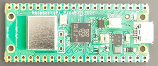
The Pi Pico sold well; the Pico W has sold out several times since its launch.

With two million units planned for production this year, the Pico shortage will be temporary, but it's a sign that the new Pico W is going to repeat the amazing success of the original Raspberry Pi.

Pico W

Why is it selling so well?

What's the secret?

Yesterday I jointed a group of friendly and knowledgeable enthusiasts for  an online meeting of the Melbourne MicroPython Meetup.

It's not just a user group. Damien George gave a talk about the Rapsberry Pi Pico W. Damien is the creator of MicroPython, and he was responsible for the MicroPython port with Wifi support. The software was available on the day that the Pico W launched.

In the discussion that followed, several of us speculated about the secret sauce that made the Pico/Pico W so successful.

We concluded that there was no single factor, but that several features combined to make them so attractive.

Seven key features

What helped to catapult the Pico and Pico W to instant success?

First: the Raspberry Pi brand. With over 40 million Pis in the hands of Makers, Programmers, Learners, Teachers and Entrepreneurs, the Raspberry Pi name is widely known, respected and trusted.

Second: Community. the Pico family is supported by a huge Raspberry Pi community of Makers, Hackers, Journalists and Vendors.

On the day of its launch companies like Pimoroni, Adafruit and the Pi Hut offered the Pico W for sale and  announced their own add-on products.  The Pico W sold quickly.

By the next day enthusiasts had started to share their exploration of the Pico W!

Tom's Hardware publicised the product from the day of its launch and was quick to share projects as they were announced.

The July 2022 issue of the MagPi magazine has articles about Pico projects, and reviews of  newly announced third party products.

Third: Great documentation, available at launch. Raspberry Pi's documentation is written by Alasdair Allen. He's uniquely qualified. He's a been a physicist, a hardware hacker and a journalist. His documentation is readable, clear and accurate, and he's quick to respond to feedback.

Fourth: Great software, available from the start.

With a full-featured, well-documented MicroPython port available from day one, the Pico W made it really easy for us to explore its potential.

Pico W strip
Fifth: Great for making new products. The castellations on the Pico and Pico W allow them to be soldered directly onto PCBs.

Picos are available in quantity, in strip packaging, as is the RP2040 chip on which they are based.

Sixth: PIO (Programmable I/O) is an amazing feature of both the original Pico and the W.

PIO has enabled all sorts of capabilities; an HDMI interface, a VGA interface, and other specialist protocols, all implemented in software

Seventh: Availability. While the Pico W has sold out a couple of times, stocks have quickly been replenished. Global chip shortages have impacted the availability of many products, including the Raspberry Pi Model 4, but the Pico has been essay to find online.

What are the Pico's competitors?

There are hundreds of similar products, but the main competitors of the Pico are
  1. Boards from other manufacturers that use the same chip - the RP2040. Boards are available from dozens of vendors, including Adafruit, Pimoroni and Arduino. Many of these have great extra features, but most cost significantly more than the $4/$6 of the Pico and Pico W.
  2. Boards from the Arduino family. The Arduino has a large and loyal following, but the original products lack the memory to support MicroPython, and more recent products are significantly more expensive.
  3. Boards based on the ESP 8266/32. These have a large following, and they are available at a very competitive price. I'm sure they will continue to hold a significant share of the market, but their market is fragmented and the boards attract much less media coverage than the Pico.

So what's the future?

The range of Pico-based projects and products is growing fast. Eben Upton (CEO of the commercial arm of Raspberry Pi) says they expect to make 2 million units this year, ant it looks as if demand will match or exceed that. The Pico is affordable, powerful, fun and available. It's a great platform.

I'm currently working on a free guide to the Pico W. Keep an eye on this blog, or follow @RAREblog in Twitter for more information.


Monday, 18 July 2022

Make your own strip-board breakout boards

A useful trick for Makers

In this article you'll see when you should build your own breakout boards, and you'll learn a useful trick to use when making them.

Breakout boards rock

Digital Makers can often make projects faster by using breakout boards.

A breakout board is a small but useful module that you can use to compose your project. There are hundreds of breakout boards available. Many are based on tiny SMD chips that are tricky to solder. You can save time and reduce the risk of mistakes by buying a ready-made breakout board.

Here's an Adafruit breakout board I used in the Raspberry Pi version of Lazydoro.

image

Of course, you can only buy a ready-made board if you can find one that does what you need,

If there isn't, consider making one!

Why bother with self-built breakouts?

Why not just put everything you need on the main project board?

There are advantages to a design that uses pluggable modules. You can usually test the module on its own, and there's a good chance that you can re-use the model (or at least the design) in future projects.

Hardware and software developers have been doing this for decades. Well-designed hardware and software modules reduce coupling, increase cohesion, and increase quality.

Here's a concrete example from a current project.

A buzzer module.

One of my projects (lazydoro) needed a buzzer.

The project is based on the Raspberry Pi Pico W, so digital outputs are limited to 3.3 volts. Some active buzzers will work at that voltage, but they sound a bit feeble. I needed to hear the buzzer in the next room, so I wanted to drive it at 5 volts.

I decided to build a module.

The module design

The circuit is simple. It uses an inexpensive BC337 NPN transistor as a switch. A 3.3 volt control signal applied to the base of the transistor runs the switch on, reducing the output voltage to just over 0 volts. That results in a 5 volt potential difference across the buzzer, which then buzzes loudly.

Here's the schematic.

image

NB: In the schematic, power, ground and the signal come in on the right!

Mark 1 - oh, dear

I built the module on a small piece of strip-board. Since you can only solder strip-board on the copper side of the board, I soldered a 3-way female header on the module and a 3-way male header on the main board.

image

It worked, but it didn't look very pretty in place.

image

Mark 2 - the trick

Luckily I remembered an old trick which resulted in a much neater version.

If you solder header pins without modding them the pins are too short to plug into a female header.

Luckily, you can push the plastic to the top of the pins so they look like this:

image

Now you can solder them to strip-board and the pins are long enough to work.

Here's the new module:

image

and here's the strip-board design. As you can see, the design fits on a standard 9-strip board, and you don't need to cut any of the strips.

image

I added a female header to the main board and inserted the new module. Here it is in place. It works perfectly and looks much better now the buzzer is on top!

image

Summary

Breakout boards are a great times-saver. If you can't find one that does what you want, it's often easy (and satisfying) to make your own.

If you're using strip-board you can easily adapt male headers to that you can solder them to the copper side of the strip-board.

Sunday, 17 July 2022

Ports and Adapters - Struggling back to Beginner's Mind

I have to admit it: I've been struggling over the last two days. 

I'm working on a write-up of a Walking Skeleton for Lazydoro, together with sample code for its Ports and Adapters architecture.

I often create a Walking Skeleton at the start of an application. Lazydoro is now in its fifth version,  there's already a finished working version, and it's difficult to 'un-know' how it evolved. Trying to create what I might have written at the start has been quite a challenge

The process has been valuable, though. I think I understand Ports and Adapters better through working on my sample code and explanation, and it's had another benefit.

I've set up an automated deployment process which I'll be able to use for future MicroPython projects.

Automating deployment

Some applications can be deployed as a single file, but small modules are easier to read and test. lazydoro now consists of 9 files in a three-directory tree, and deploying a new version manually has become a real pain and is prone to error.

The new process uses a gist on GitHub which deletes all the files from a MicroPython-based board. It's always possible that your code relies on a file that you deployed a while back but have now forgotten about - a common cause of 'It works on My Machine'. 

Deployment to an empty file system is the safest way of avoiding that.

There's more to the deportment task than that, and I'm documenting the whole malarkey.

What's coming

I'm not sure how soon I'll have all the sample code ready, but you'll get to see three things:

  1. The automated deployment process
  2. The Walking Skeleton, and what you risk without one
  3. Ports and Adapters in an Embedded Application, and how that architecture helps with unexpected change.
Meanwhile I will be posting a short article about a simple technique for making stack-able breakout boards using strip-board. It's a very simple trick I forgot to apply to lazydoro until this morning; the buzzer break-out board now look much neater. 


Friday, 8 July 2022

Raspberry Pi Pico W project plans

Please help me choose!

The announcement of the Raspberry Pi Pico W has opened up a huge range of fun, exciting projects.

image
Pico W in the cloud
I've a long list of candidates, and I'm hoping for advice about which ones have the widest appeal.

The first project is a shoo-in, not least because it's almost finished. I'll tell you about that shortly. I have seven other projects pulling for my attention, and I'll give you a quick introduction to each. Then I hope you can help me chose which to do next, or even suggest an alternative.

I'll open up polls on Twitter and Facebook, but I'd also welcome feedback on this blog.

Project number One

If you're a regular reader of the RAREblog you will already be familiar with Lazydoro, my automated Pomodoro timer. The current version is now running well, but it's based on a Raspberry Pi Zero. I'm migrating the project to the Pico W for two reasons:

  1. I want to keep a daily log of my Pomodoros, so I need wifi access
  2. A new Raspberry Pi is a rare thing at the moment, because of the chip shortage.

In contrast, the supply of Pico Ws is fine. If you want to build your own Lazydoro you'll find it easy to get all the necessary hardware, and you'll pay less for it!

I'll blog about the hardware and software as soon as I've finished the migration - but after that I wonder what to build next.

After that?

These are the next projects I have in mind, in alphabetical order.

All of them are simple and inexpensive.

Which would appeal to you? And what other projects would you like me to build?

Digital Callipers

I've had a set of Digital Callipers for ages, and I love them.

image
digital callipers

They work well, but I find it annoying having to manually record dimensions. I've used the callipers to capture the sizes of new boards that I was adding to the library for Breadboarder.

What I'd like, ideally, is to be able to press a button on the callipers that captures a measurement and simultaneously triggers a photo of what's being measured.

There's an article on Hackaday that shows how to capture measurements with a PIC micro. I'm sure I can do it with the Pico.

Logic Analyzer

I have several items of test equipment that I use to track down issues with I2C and Serial comms, but they take a while to set up and the interface is never quite what I want.

I like the idea of a web-based interface that I can tailor to my needs. I could use the GPIO pins on a Pico W to track digital signals, but if I used an MCP23S17 I could monitor up to 16 signals in parallel at the speed of SPI.

I know I'd find that useful. Would you?

The Microwriter

Back in the early 1980s word processing was all the rage. If you wanted to write text on the move your options were limited. One popular solution was a chording keyboard device called the microwriter

The original microwriter
micowriter

Rumour has it that the microwriter was particularly popular with James Bond's colleagues. In the 1980e chaps like James couldn't type but apparently Q convinced them that the microwriter was cool to use - a sort of Typist's Aston Martin.

I'd love to create an updated microwriter. You could display the text you type on a cheap monochrome OLED, store the text in flash and use wifi to upload it to your laptop or workstation.

The Intelligent Breadboard

This is another project I've had on hold for ages.

The idea is simple: connect the strips of a breadboard to something which can montor (and perhaps set) the voltage of each strip.

It's a simple form of Automatic Test Equipment (ATE).

The first version of TIB (The Intelligent Breadboard) would have two MCP23S17s connected to the strips of a mini breadboard with 170 tie points.

image
mini breadboard

Later versions could add analogue voltage measurement and connect to a larger board. You could even program TIB to check your wiring step-by-steo when prototyping a new project.

A Web-based Oscilloscope

Years ago, when the first mbed board came out, I wrote a project that created a web-page showing a varying voltage. I used svg to generate the graphics. It worked surprisingly well. Time to update that for the Pico W?

The first version would be for audio frequency signals only, but it would be interesting to see how rapidly one could capture analogue signals. I'd want to wrap some high-performance ome C code as an .mpy file. I've not tried that, and it would be a useful skill to learn.

SLAMbot

SLAMbor is a mobile robot. Not one that slams into things, but one that does SLAM: Simultaneous Location and Mapping.

You'd control the robot from your phone, and it would use a set of 8 VL53L0X ToF sensors to build a map of its environment as you drove the bot around a room.

Weather Station

I'd love to build a web-connected weather station around the BME280. I'd also like an anemometer to measure wind speed. I've recently come across a couple of promising designs that could be built without a 3D printer.

Over to you

I'm looking forward to a lot of Pico W fun over the next few weeks!

I'll post a list of the projects on Twitter and ask for your vote. It will have to be a pair of polls as I think Twitter limits us to 4 choices.

Alternatively, you can let me know what you'd like to see as a comment on this blog.

Tuesday, 5 July 2022

Lazydoro is working again!

Yesterday things looked tricky.

I realised this morning that I could easily fix the problem I've been having with lazydoro and my new chair.

Doh! All it took was an adjustment to the distance threshold.

Lazydoro is now sitting by my keyboard and keeping a watchful eye on me.


lazydoro back at work

Next steps: keep a log of Pomodoros completed/broken.


Monday, 4 July 2022

Lazydoro Mk 3 - lots of automated tests for a simple design

At the end of  yesterday's post lazydoro was running on a Pi zero still not working reliably.

In November 2021 I worked on Ness Labs' Write a book in 30 days challenge.

I had to rely on a web-based Pomorodo timer, and thought I'd have another try at the lazydoro project.

I decided to rewrite lazydoro from scratch.

Lazydoro needs to do four things.

  1. It needs to know when I arrive at or leave my desk
  2. It needs to keep track of passing time
  3. It needs to know where I am in a Pomodoro cycle
  4. It needs to provide feedback to keep me on track.

To make lazydoro easy to test I used a variant of the Ports and Adapters architecture. (Ports and Adapters is sometimes called Hexagonal Architecture).

I first came across it in an article by Alistair Cockburn, and it made a lot of sense. It's also featured in the GOOS book: Growing Object Oriented Software Guided by Tests.

Simple architecture

Here's the architecture for lazydoro:

image

At the centre is the application model: the Pomodoro object. That contains code that keeps track of where I am in the Pomodoro Cycle. It's a state machine, and it changes state based on my presence or absence and the passage of time.

The Pomodoro model gets inputs from a ClockWatcher.

The ClockWatcher gets a tick that tells it time has passed. It then asks the rangefinder how close the nearest object is, and from that it works out whether I've just arrived at or left my desk and sends a message to the Pomodoro object as necessary .

As the Pomodoro tracks the various states (waiting to start, in a Pomorodo, waiting for me to begin a break, on a break, or waiting for me to return). it updates the Display, turning LEDs on or off and sounding the buzzer as appropriate.

The great advantage of that  approach is that I can easily test the application. I can send a message pretending that a second has passed as often as I like. That's really helpful because it allows me to run a test much faster than real time. A real Pomodoro cycle takes 30 minutes: 25 minutes of work and a 5-minute break. I can simulate a full cycle in under a second if my fake clock ticks fast enough.

Mock Objects

The automated tests use Mock Objects to represent the RangeFinder and Display.

As a result, the tests are simple and expressive. Here's the test code for a full Pomodoro cycle:

def test_tracks_full_pomodoro(self):
    # main success scenario
    self.person_absent()
    self.wait(seconds=1)
    self.check_leds_are_off()
    self.person_present()
    self.check_leds_are_off()
    self.wait(seconds=10)
    assert_that(self.display, shows_only(BLUE))
    self.wait(minutes=24)
    assert_that(self.display, shows_all(BLUE))
    self.wait(minutes=5)
    assert_that(self.display, shows_all(RED))
    self.person_absent()
    self.wait(seconds=20)
    assert_that(self.display, shows_only(GREEN))
    self.wait(minutes=1)
    assert_that(self.display, shows_only(GREEN, GREEN))
    self.wait(minutes=1)
    assert_that(self.display, shows_only(GREEN, GREEN, GREEN))
    self.wait(minutes=1)
    assert_that(self.display, shows_only(GREEN, GREEN, GREEN, GREEN))
    self.wait(minutes=1)
    assert_that(self.display, shows_only(GREEN, GREEN, GREEN, GREEN, GREEN))
    self.wait(minutes=1)
    self.check_leds_are_off()
    self.person_present()
    self.wait(seconds=20)
    assert_that(self.display, shows_only(BLUE))

Success at last?

It worked well for weeks, and I used lazydoro every day.

And then it stopped working.

What went wrong?

The code was fine. The problem was physical.

I got a new chair for my study.

It had much better support for my back, but lazydoro's ToF sensor sometimes thought the chair was me! It picked up a reflection from the back of the chair, and it sometimes thought I was at my desk doing a Pomodoro even when the chair was empty.

A new beginning

I needed a new approach.

I decided to ask for help in one of the Facebook groups I belong to, and got lots of interesting suggestions.

Tomorrow I'll reveal what happened next.

Sunday, 3 July 2022

Lazydoro migrates to the Pi

In the previous blog post I described cushadoro and its successor, lazydoro Mk 1.

That was the first version of lazydoro, implementedin CircuitPython and based on the Adafruit Trinket M0. Today I'll describe the next stage of the project, a Raspberry Pi-based version.

I made real progress but, as you'll see, lazydoro was still not quite good enough.

Lazydoro needed unit tests

At the point were we left the project the Python code had become a little complicated. I thought I ought to do more automated testing.

It's possible to do that on CircuitMpython devices like the Trinket M0, but it's a lot easier if you canuse the standard Python libraries, including Python's unittest and mock frameworks.

I decided to migrate the project to a Raspberry Pi.

Moving to the Raspberry Pi

image
Explorer HAT prototype
At the time I migrated the project I had just fallen in love with Pimoroni's brilliant Explorer HAT pro. The HAT has loads of useful peripherals, and needs no soldering, so it's great for learning and for rapid hardware protoyping.

I liked the Explorer HAT so much that I wrote a book about it!

The first version of Lazydoro Mark 2 used an Explorer HAT, a VL53L0X sensor and a buzzer for feedback.

Migrating the code with Adafruit Blinka

Adafruit's VL53L0X library is written for CircuitPython, but the clever folk at Adafruit have come up with a library for the Pi called adafruit-blinka.

Blinka allows you to use Adafruit's CircuitPython's device libraries on a Raspberry Pi or a Jetson Nano. I found I could move the sensor code from the Trinket to the Pi without change.

I did make one change, though, taking an opportunity to enhance the hardware.

Adding the Pimoroni Blinkt!

image
Pi zero version with Blinkt!
I replaced the Trinket's single NeoPixel with a Pimoroni Blinkt! display.

The Blinkt! has a bank of 8 multi-colour NeoPixels. There's a Pimoroni library that can set the colour and brightness of each display.

That allowed me to show how much time had passed during a Pomodoro or a break.

The project doesn't need a lot of computing power, so I decided to run it on an inexpensive Raspberry Pi Zero.

Once I had a working prototype I transferred the design to an Adafruit perma-proto bonnet.

That was good enough to demonstrate.

Featured on Hackaday!

I showed it off at a Raspberry Pint Meetup, and posted the project on Hackaday.io. To my delight it got featured, and quite a few people showed interest.

I might have stopped there, but I didn't.

The Mark 2 version was good, but not quite good enough.

Lazydoro - usable but not ideal

I used Mark 2 intermittently, but it wasn't perfect.

The ToF sensor still returned occasional spurious readings. Some were easy to fix.

The sensor sometimes returns a distance of 0 instead of the 8191 reading that means 'out of range'.That looked like an off-by-one error in the library or the hardware! I wrote a simple fix for that problem, but I found I still got occasional spurious readings.

I found the necessary change was harder that I'd hoped. I made a few attempts, but I used lazydoro less and less, and I eventually accepted the frustrations of using a web-based timer.

In November last year I started work on a new book: Give Memorable Technical Talks.

I did a lot of Pomodoro-based writing, and I longed for a better Pomodoro timer.

Next - Lazydoro Mark 3

Want to know how the search for a timer went? Look out for more revelations in the next thrilling episode!

Saturday, 2 July 2022

The Lazydoro story - Part 1

The Lazydoro

Lazydoro is potentially the most useful project I've built.

I use the Pomodoro method when I am writing or coding. It keeps me focused, and makes it easy for me to maintain progress. The Pomodoro technique involves working for 25 minutes without interruption, followed by a 5-minute break away from your desk. It helps with productivity, and it's good for your health.

There's just one problem. You need to remember to start a Pomodoro timer!

Using a timer

When I first started using the technique I tried using a web-based app to keep track of time.

Sometimes I remembered to use it, but sometimes I forgot. If I was deeply absorbed in what I was doing I lost track of time and failed to take my break. After a few days of that my mood and my knees suffered!

I tried building some hardware to make the Pomodoro technique easier to use.

Cushadoro
image
Cushadoro

I started the project back in 2015. I called that version cushardoro - an Adafruit trinket attached to a resistive pressure sensor located in a cushion on my study seat!

It worked after a fashion, but it had several practical drawbacks. It required me to put some rather uncomfortable hardware in the cushion on my chair, and it was not very reliable. Sometimes it failed to notice me when I sat down, I had to make sure the battery was fresh, and the buzzer was the only form of feedback.

I also found it quite a challenge to program using the Arduino C-based environment. I'm not very comfortable programming in C, and I miss having a REPL for rapid feedback as I code.

I archived the project and forgot about it.

image
Lazydoro Mk 1
Lazydoro is born

Back in 2018 Richard Kirby posted in the Raspberry Pint forum about his experiments with a ToF (Time of Flight) sensor.

I wondered if the sensor would work for my Pomodoro timer. Could I use a ToF sensor to check if I was in my chair ? I bought a VL53L0X sensor and tried it out.

It looked promising, and in February 2019 I started working on a prototype. It used the Adafruit Trinket M0, which I could program in CircuitPython.

The prototype had one input device (the distance sensor) and two output devices: the on-board NeoPixel display and a buzzer.

The application just checked the distance from lazydoro to the area in front of my keyboard.

When I was at my desk I was about 30 cm away; when I was taking a break the distance to the wall behind me was over 1 metre.

The application checked the distance and used that and the CircuitPython time.sleep() method to work out how the Pomodoro was going. It provided visual feedback using the on-board NeoPixel. When I was on a break it drove a buzzer to tell me when it was time to return.

The VL53L0X ToF distance sensor worked fairly well but there were occasional glitches when the sensor seemed to misread this distance. I asked Richard if he'd seen similar behaviour, and he had.

I tried to track the problem down but eventually gave up. I switched to another project and left the hardware in its project box for another year.

In January 2020 I decided to have another go.

Find out what happened in tomorrow's exciting episode!