Pages

Friday, 28 February 2020

An I2C keypad for the micro:bit - part 2

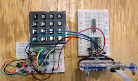
A working prototype
I've now got a home-brew Arduino clone reading the keyboard and sending key-presses to a micro:bit using I2C.

Preparing the Arduino clone was trickier than usual.

As I mentioned in yesterday's post, the Arduino needs to run at 3.3 volts. That's the working voltage (Vcc) for the micro:bit, the Pi and the Jetson Nano. Connecting I2C lines from a 5v device would damage them, so 3.3 v operation is essential.

I have a good stock of ATmega328P chips left over from the days when I was running Shrimping workshops. The ATmega328P  works well at 3.3 volts, so long as the clock frequency is no more than 8 MHz. Most Arduinos run at 5v with a clock speed of 16 MHz, so there's work to do.


8 MHz clock issues


If I2C is to work reliably at 8 MHz the Arduino needs to be configured for an 8 MHz clock, and it needs a bootloader that works at that clock rate.

My first step was to wire up a working clone on a breadboard with an 8 MHz crystal and install the correct bootloader.


Installing the bootloader


These days it's pretty easy to burn a bootloader on an ATMega328. The Arduino IDE has a bootloader-burning sketch; I connected a Uno to my clone, following the excellent instructions on the Arduino website. I specified the target board as an Arduino pro mini with a 382 chip and 8 MHz clock and installed the bootloader.

Programming the Arduino clone


Once I'd done that I had a functioning, programmable clone running at 8 MHz on my breadboard. I wired it up to the keyboard and dug out a 3.3 volt FDTI cable.

Using the Arduino IDE and the FTDI cable I programmed my clone and did a smoke test to make sure that it was working. I'd modified the I2C keyboard sketch so that it flashed the on-board LED on start-up, and turned the LED on whenever the keyboard buffer filled up. I installed the sketch and verified that the keyboard was working.

Testing the keypad


Nearly there! I wrote a simple micropython test program for the micro:bit and connected it to the clone board. Using the mu REPL I could see the output from the keyboard. I've got the rows of the keyboard inverted, but that's easy to fix. The core is working and my next step will be to transfer the clone to an Adafruit perma-proto board, add a Grove connector, and document the whole construction and programming process. I've already added the Arduino and micro:python code to the babelboard software repository.

The micro:bit code


The microbit code is pretty simple.
from microbit import *
from time import sleep


class Keyboard:
    def __init__(self, addr=0x08):
        self._addr = addr

    def read_char(self):
        return i2c.read(self._addr, 1)


def run():
    kbd = Keyboard()
    while True:
        key = kbd.read_char()
        if (key != b'\x00'):
            print(key)
        sleep(0.01)

run()


I'll add comments and more code so you can use the keyboard with a Pi, an Adafruit CircuitPython board or a Jetson Nano.

Don't forget to follow @rareblog on Twitter if you want to see the final write-up!

Thursday, 27 February 2020

An I2C keypad for the micro:bit - part 1

I love the micro:bit. It's affordable, it runs micropython, and it's instantly engaging. These days it's supported by a huge range of add-ons that extend its capabilities, but there's always room for more.

A lot of the add-ons that I buy or build use are based on the I2C protocol. I2C is a  widely-supported way of connecting and controlling add-on boards to single board computers like the micro:bit, Arduino and Raspberry Pi.

There's lots of sample I2C code for the Arduino and the Pi, but not so much for the micro:bit. A few days ago I posted about an experiment connecting a micro:bit to a numeric keypad using I2C. That worked well, and the code is on GitHub. As you can see, the program needed quite a bit of code, and space on the micro:bit is at a premium. Since I wanted to add an LCD display I started looking for a more compact approach.

Help from Arduino


I decided to try out a design that used a home-brew Arduino clone to scan the keypad and make key-presses available with a simple I2C interface.

I'd previously used Arduinos in I2C slave mode, and there's a great example in the Arduino docs. Next I found a keypad library that looked as if it would fit the bill. It handles 3x4 and 4x4 keypads and it deals with contact debouncing.

Since the client can look for a key-press at any time, and the user can press a key whenever they want, my code includes a ring buffer to store key-presses until they are asked for. I used code from this excellent article on Hackaday.


The Uno Protoype


I put together a prototype using two Arduino Unos, one acting as a slave and one as the master.

It worked, and I've added the code and a fritzing diagram to the babelboard software project. It should be a simple matter to replace the slave Uno with a home-brew Arduino clone, but I've got one minor challenge to overcome.

The Uno runs on 5 volts, but the micro:bit and the Pi use 3.3 volt signals and 5 volt inputs will damage them. I'll need to run my Arduino clone on 3.3 volts. It's not hard, but causes a few complications. I'll describe them (and, I hope, the solutions) in the next blog post.

Follow me  (@rareblg) on twitter if you want to catch the next exciting episode :)


Friday, 21 February 2020

Adding a DS1307 Real Time Clock to Raspberry Pi

Grove RTC
The DS1307 RTC (Real Time Clock) is widely available, but adding one to a Raspberry Pi turned out to be a bit of a Yak shave.

I'm gradually adding code and wiring instructions to my babelboard hardware and software projects, and I thought it was time to cover an RTC.

I had a Grove RTC board from years ago and decided I'd document connecting that to a Raspberry Pi.

The need for Battery Power


First Yak Shave moment: RTCs normally use a coin battery to maintain power so they can keep time when their host is off, and the battery in my Grove board was way past its use-by date.

This happened on Sunday evening, and the local supermarkets were shut, but the local convenience store was open. No CR1220, though, so I had to wait until the next day to get started.

While I was waiting I read the data sheet for the DS1307 chip and realised I had another problem.

Don't connect this chip directly to your Pi!


Seeed Studios describe the DS1307 breakout as Pi-compatible, and so it is, if you connect it via a GrovePi board. The DS1307 is an I2C device and it requires a 5 volt supply.

If you do a direct connection to the Pi's I2C pins and apply 5v to the Grove RTC board, the pullup resistors will apply 5v to the Pi and bad things will eventually happen to the Pi.

Babelboard to the rescue


babelboard
One of my babelboards is designed to fix this very problem. It connects to the Pi header, but it has two Grove I2C connectors.

One is directly connected, so it runs at 3.3V.

The other is connected via a level shifter. It provides a 5v supply and handles 5v on the SDA and SCL I2C lines, but the level shifter means that the Pi only ever sees 3.3 v signals.

That's just what's needed for the DS1307, so I thought I was away to the races.

Not so fast!

Numpy? Why?


why numpy?
I installed the Grove script for the DS1307 and tried to run it. I got an error message telling me that Python couldn't find numpy.


What? Why does an RTC program need numpy's fast array handling?

It turns out that the Grove software assumes you want to install the whole Grove library, and everything depends on a Grove package, which in turn needs numpy for one particular board!

working output
Fortunately Adafruit has code to drive the DS1307 on the Pi. Once I'd installed that I could interface with the RTC and everything went swimmingly.

I'll document what I did and add it to the babelboard projects over the weekend.

After that, I'm an I2C keypad reader which uses an Arduino to do the heavy lifting, followed by a similar I2C 'old skool' LCD display. I'll post about those when they are ready.

If you're based in London, I'll be talking about micropyhon, CircuitPython and Blinka at the Raspberry Pint meeting at the Microsoft Reactor next Tuesday (25 Feb). There are other interestin talks; you can sign up here.


Saturday, 15 February 2020

I2C and SPI on the micro:bit; additions to the babelboard range

micro:bit Keypad using I2C+ MC23008
For some reason there's not a lot on the web about using I2C and SPI with the BBC micro:bit.

The I2C and SPI protocols allow single board computers like the micro:bit, the Raspberry Pi and Jetson Nano to drive hundreds of different types of useful peripheral chips.

There are lots of widely available drivers for the Raspberry Pi, the Arduino and  Adafruit boards. I've seen fewer for the micro:bit, and I have started writing some more as part of my babelboard project. I am also building a babelboard for the micro:bit.

The babelboard project


Babelboards allow you to connect a range of I2C and SPI devices to several popular single board computers.

The image on the right shows an mcp23S08 reading a hex keypad driven by a micro:bit using SPI.

The micro:bit babelboard allows you to connect Grove I2C devices and the Quick2Wire port expander and analog boards. You can get adapters that connect Grove to Qwiik, so you can also connect the range of Qwiik devices to the micro:bit. Planned enhancements will make it easy to connect to the Pimoroni breakout garden range, and the Adafruit STEMMA/STEMMA QT ranges.
A babelboard for the Jetson Nane

Existing babelboards allow you to connect I2C and SPI peripherals  to the Raspberry Pi, the Jetson Nano and Adafruit feather range. Since the Adafruit Clue has a micro:bit compatible pinout you'll be able to connect to that as well.

Most of these exist as prototpyes at present, but the designs are Open Source and I'll be publishing them as part of the babelboard hardware project. Some use stripboards, some use Adafruit permaProto boards, and a growing number use custom PCB designs created in Fritzing or KiCAD.

Connecting the hardware is not much use without software to drive it. If the the computer you're using supports CircuitPython or Adafruit Blinka you've got all you need to start using any device included in the CircuitPython library.

I'll be adding code to drive things from the micro:bit as time permits, and I'll also be adding code for more of the Grove peripherals.


Wednesday, 12 February 2020

The bistable flip-flop 60 years on

flip-flop from 'Electronic Computers'  - T.E. Ivall
About 60 years ago I started to teach myself about how digital computers worked. I'd already written some simple programs and I wanted to build a computer of my own. In 1960 that was a bit ambitious, but I did manage to build a few simple digital circuits including a flop-flop. (A few years later I hand-wired a core store, but that's another story).

The flip-flop lies at the heart of digital electronics.The thing that makes digital computers so powerful is memory. Memory  can store the data that programs work on, and it can also store the the programs themselves. Early computers used a variety of techniques for storage but almost all of them used flip-flops to some extent.

The bistable flip-flop is a very simple circuit. It can store a single binary digit (bit) of information.  The flip-flop was not new in 1960. The original patent was granted to the inventors (Eccles and Jordan) in 1918. That was long before the transistor was invented: the first flop-flops used valves (US: vacuum tubes).

Valves were still used in computers in 1960, but transistors were beginning to replace them. Transistors were expensive but I managed to buy a few from Proops*, a famous electronic components store in Tottenham Court Road, and I soldered two transistors together with a few other components to make a flip-flop.

* Proops still exists, albeit in a rather different format. They now support hobbyists, jewellers, craft makers and modelling enthusiasts, and run a mail order business from rural  Leicestershire.


A bistable flip-flop is a symmetrical circuit. At any given time one of the transistors is 'on' and the other 'off'. In an S-R flip-flop (the one I made back in 1960) a pair of buttons allowed you to put the flip-flop into either of its stable states.

I had to check the output using a multimeter; the transistors I used couldn't drive a light bulb, and LEDs were not yet invented.

A few days ago I decided to recreate the circuit using modern components. I started with a breadboarded version but since then I've built a more permanent flip-flop using stripboard. The layout reflects the symmetry of the circuit.

The physical version is reassuringly similar to the fritzing design.

Modern memory is based on a more complex version of the circuit, and modern computers contain a lot. You'd need 8 billion flip-flops to store a Gigabyte of data!

In last Wednesday's #MakersHour session on twitter, someone suggested that we should be capturing knowledge of original computer technology while olders like me are still around to recall it. Tweet to me (@rareblog) if you'd like to see more about early computer technology!

Adafruit Clue - love at first sight

My Adafruit Clue has just arrived, and I am delighted with it.

The Clue is a small single board computer that has the same format and connectors as the BBC micro:bit. It's more expensive than the micro:bit but it's a much, much more capable device.

micro:bit Pros and Cons 


I still love the micro:bit. It invites you to interact with it as soon as you power it on and it's introduced a huge audience to the pleasures of programming.

There are a range of programming options for the micro:bit, including micropython, and it's easy to program using the free mu editor.

 However, it has some frustrating limitations.

The micro:bit's 5x5 LED display is cute, but scarcely high-resolution. There are a few on-board sensors - an accelerometer and a magnetometer - and you can coax the processor chip into telling you how hot it is. It has a couple of buttons, and it supports radio communication with other micro:bits. But that's all.

It also has quite limited memory which can limit the complexity of the programs you write.

The micro:bit hardware has Bluetooth support, but its limited memory means that Bluetooth is not accessible from micropython.

The Clue blasts those limitations away.

Clue Power


Like the micro:bit, the clue can be programmed in Python. It supports CircuitPython, Adafruit's fork of micropython. That means that you get access to a library that's well documented, works reliably and supports a huge and growing range of peripherals from Adafruit and third parties. There's on-board Bluetooth and CircuitPython provides easy access.

My personal preference is to develop in Python but there's also support for the Arduino development environment.

The Clue has a great selection of peripherals on-board. Like the micro:bit, it has an accelerometer and compass, but it also has a gyroscope. You'll also find a light/colour/gesture sensors, a microphone, a buzzer and sensors to measure temperature, humidity and pressure. For me, though, the thing that instantly captured my heart was its crisp, colourful 1.3″ 240×240 TFT display.

Quick Start


Overall impressions of the Clue have been great. The hardware is very capable, and Adafruit's documentation is superb. Even if you have no Python experience, the Getting Started Guide will have you writing and running simple Python programs on the Clue in no time.

I bought an early alpha version of the Clue which has sold out. PyCon US attendees will be getting one as a freebie thanks to Adafruit and Digi-Key.
 It may be a little while until  the final production version is available but it will be worth the wait!

I'm currently working on some I2C applications on the original micro:bit, and I need an I2C monitor to help me troubleshoot. I have a couple of PC-based scopes that could do the job, but I think the Clue is up to the task, and it would be a fun project. I'll report on progress.