Pages

Wednesday, 25 March 2015

More fun with the Pimoroni Explorer HAT


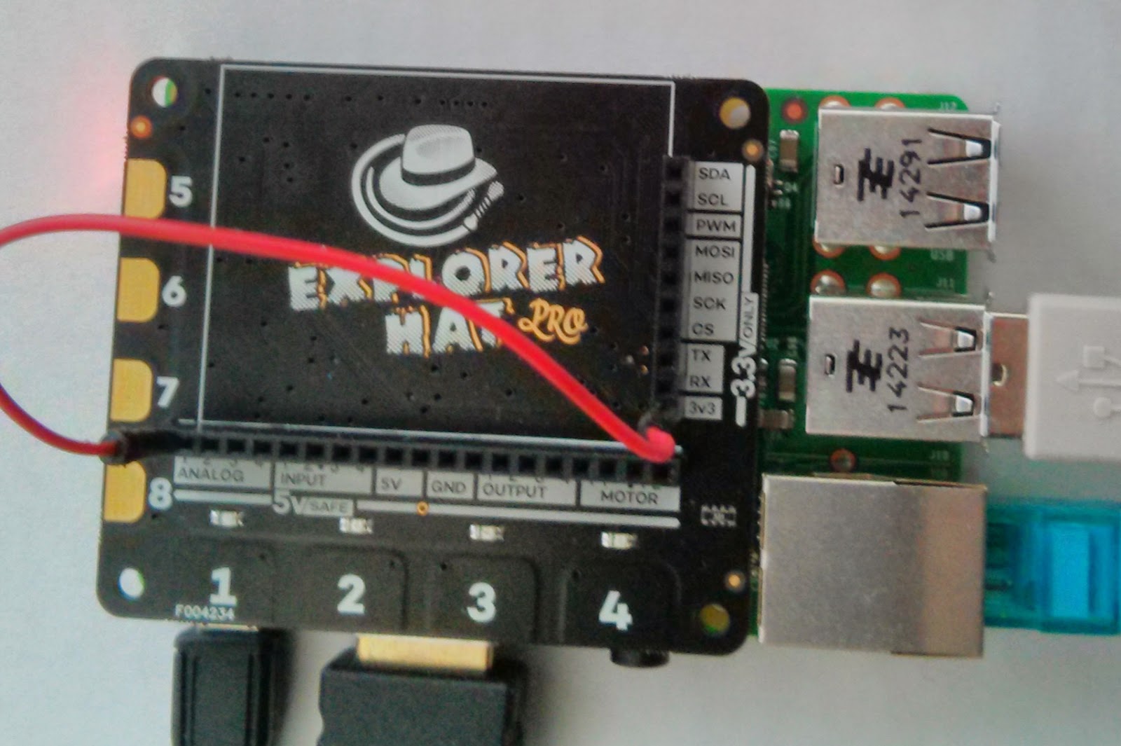
I've been playing a bit more with the new Pimoroni Explorer HAT.

One of the most exciting features of the Pro version is the analogue interface.

Once you've installed the ExplorerHAT package using pip, you can try typing in the examples in the README on github.

If you want some more examples, you can clone the github repository into a directory of your choice. Then you'll be able to run the code from the examples directory. Type

git clone https://github.com/pimoroni/explorer-hat.git
cd explorer-hat
sudo python examples/analog-event.py

You'll see a series of rapidly varying numbers displayed in the console. These show the current voltage as seen on analogue input 1. Since you (presumably) haven't connected that to anything, the output will be fluctuating random values.

To see something more sensible, use a jump wire to connect analogue input 1 to the Hat's 3.3 volt output, and you should see the display stabilize showing a value of about 3.3

The github repsoitory now contains an experimental fritzing library containing parts for the HAT and Pro HAT; I used the Pro version to create the diagram above.

I'm really excited by the Explorer HAT. I will blog some more about it as I play, and I am going to use the blog posts as the basis of an inexpensive Experimenter's e-book. If you might be interested, sign up here and I'll let you know when the book is available.


Tuesday, 24 March 2015

Pimoroni Explorer Pro Hat - first impressions

This morning my new Explorer Hat from Pimoroni arrived, and the tempation to play has proved to much to resist.


There are two versions of the Explorer Hat, standard and Pro. I greedily ordered one of each; the standard version is great for experimenting, but the Pro version offers several extra useful features.

I started with the Pro.

I love it.

Here's what the Explorer hats provide:
  • Four buffered 5V tolerant inputs
  • Four powered 5V outputs (up to 500mA!)
  • Four capacitive touch pads
  • Four capacitive crocodile clip pads
  • Four coloured LEDs
  • PRO ONLY Four analog inputs
  • PRO ONLY Two H-bridge motor drivers
  • PRO ONLY A heap of useful (unprotected) 3v3 goodies from the GPIO
  • A mini breadboard on top!
It took me a couple of minutes to get the environment set up
The Readme on the github site tells you how prepare your Pi, and then walks you though some fun experiments.

One thing to watch: the setup instructions suggest that you install pip by typing
sudo apt-get install python-pip

Just say no

I recommend that you don't install pip that way. The version of pip that's included in the raspbian distribution is quite old, and it will bring python2.6 in with it! With yet another version of Python on your pi, the possibilities for confusion are considerable, and using the outdated version of pip can cause other problems.

Instead, I recommend that you start by installing setuptools and use easy_install (part of setuptools) to install pip. Here's what you need to type:

sudo apt-get install python-setuptools
sudo easy_install pip

and now you can type

sudo pip install explorerhat

Apart from that, the installation instructions are fine, and very clear.

Once you've configured i2c and installed all the required software, you can start to flash LEDs and write code that responds to button presses.

Lights On!

Here's the Python code to turn the red led on:

explorerhat.light.red.on()

That's simple and intuitive. I'll bet you can guess how you turn the red light off, and the blue light on :)

I suspect you'll find that the Explorer Hat makes it as easy to do Physical Computing on the Pi as it is on the Arduino.

You'll be programming interactively in Python instead of editing, compiling and uploading code in the Arduino's c-based Wiring language. Many people will find that development is faster and the learning curve is less steep.

I think Pimoroni have a real winner here, especially at the very attractive price. The Pro is £18, and the standard Explorer Hat is just £10.

Spread the good news! You can share this post using the buttons below.

Friday, 20 March 2015

Using the Raspberry Pi SPI as an AVR ISP (In-system programmer)

A few days ago I blogged about using the Arduino IDE on the Raspberry Pi. It works fine, but of course the Arduino or clone needs to have a boot-loader installed in order for the IDE to work its magic.

I wondered if you could also use a Pi to install the boot-loader in the first place. There are lots of ways to install a boot-loader, but most of them require that you start out with at least one working Arduino or clone. What if you don't have one? Could you use a Pi as a programmer?

(c) Jason Mann
I'd recently seen a rather cool project which uses a custom board with an ATTiny AVR chip and an LED display to show the Pi's IP address.

Jason Mann, the author, explained how he used the Pi to program the ATTiny.

It looked to me as if his technique should work just as well on an ATMega 328p. (That's the chip that forms the heart of the Arduino Uno and the Shrimp).

It does.

I hit some minor complications while getting things to work and thought I should share the solutions here.

The Software

In order to install the bootloader I used avrdude. This does not support programming using the Pi's SPI port out of the box, but there's a forked version written by Kevin Cuzner which does.

Enabling SPI

Jason's article refers to an old way of configuring the Pi to use SPI ports. The raspi-blacklist.conf file appears to have disappeared. Instead, this article describes three ways of enabling SPI.

I went for the simplest, ran sudo raspi-config, selected the option to enable SPI, and rebooted.

I followed  Kevin Cuzner's instructions to build his forked version, and then realised that I had another potential problem. I now had a modified version of avrdude in the /usr/local/bin directory, but I also had an un-patched copy which the Arduino IDE had installed.

Luckily, the Arduino IDE finds its own version because it comes earlier in the search path, so the IDE still works perfectly. To use the patched version I referred to its location explicitly. You can see that in the example at the end of this post.

The Hardware

Jason's project runs the ATTiny at 3.3 volts but the Arduino normally runs at 5v. While you can just about get away with directly connecting a 5v Arduino to a Pi if you're using I2C, you cannot do so using SPI.

I had an Adafruit Pi Cobbler+ and couple of SparkFun level shifters lying around. I connected the Pi via the cobbler to the shifters and the shifters to the Arduino. You can see a picture at the top of the page.

Trying it out

I ran

sudo /usr/local/bin/avrdude -c linuxspi -p m328p -v -P /dev/spidev0.0

Here was the tail of the response:

         Programmer Type : linuxspi
         Description     : Use Linux SPI device in /dev/spidev*

avrdude: AVR device initialized and ready to accept instructions

Reading | ################################################## | 100% 0.00s

avrdude: Device signature = 0x1e950f
avrdude: safemode: lfuse reads as FF
avrdude: safemode: hfuse reads as DA
avrdude: safemode: efuse reads as 5

avrdude: safemode: lfuse reads as FF
avrdude: safemode: hfuse reads as DA
avrdude: safemode: efuse reads as 5
avrdude: safemode: Fuses OK (E:05, H:DA, L:FF)

avrdude done.  Thank you.

More detail

This post is already long enough. If you want the full details of the installation and build process, along with a fritzed diagram of the breadboard connections, I'll be posting them in next Friday's free newsletter.

You can sign up for the newsletter here.

Thursday, 19 March 2015

Arduino e-Book - reviewers wanted. Might you be one?


. romillycocking_cover-scaled-small.jpg

I’m about to publish an e-Book for Arduino Experimenters

It’s called Life after Blink!

I’m looking for a small team of reviewers who can check it over for bugs and suggest improvements.

Might you be interested?

The book describes 5 experiments:

  1. Fortune Cookie server
  2. Morse flasher
  3. Counter/LED ripple display
  4. Button and Buzzer
  5. LDR (photocell)  and bar level indicator

The experiments use readily available components, but there is a kit of parts available for those who prefer.

If you are selected as a reviewer you will get a free copy of the kit, and you will get a free copy of the e-book with updates throughout its lifetime.

If you think you might enjoy reviewing Life after Blink, click here to register your interest. I’ll send you a link to a short online survey. There’s no obligation, I won’t spam you, and you’ll get 75% off the price of the book even if you don’t review it.

Tuesday, 17 March 2015

neo4j and Social Media Scraping for twitter, Stack Exchange and Github

I've been experimenting for the last couple of days with tools to help me identify experts and their comments in particular technical areas. I'm hoping to combine data from twitter, stack exchange and git-hub in a way that allows me to look for people who have
  • tweeted about a topic
  • posted answers on StackExchange or
  • published relevant code on GitHub
I'm also interested in how they interact.

There's a relevant demonstration using clojure and Ruby described on the neo4j blog, and I am using that as a basis for my Python development.

If you're not familiar with neo4j, it's a graph datase. Visit their site to find out what that term means if it's new to you. What matters is that it's a great way to store and quesry social replationships and social meida activity.

I'll report on progress, but one of my jobs for tomorrow will be to see how usable my code is on the Raspberry Pi 2.


Thursday, 12 March 2015

What would you like to know about Pi + Arduino?

C3Pi
Regular readers will know how much I like the combination of the Raspberry Pi and Arduino.

C3Pi is a prime example of that approach.

There's lots to say about using the two platforms together.

I just started a poll on G+ asking which aspects people are most curious about.

Have your say here!

Monday, 9 March 2015

Scheduling on the Arduino

I'm currently working on a project that requires an Arduino to
  • monitor the positionof two rotary encoders
  • monitor the state of set five push buttons and
  • send the state of everything over a Serial link whenever something changes
This is not as simple as it seems.

All of the components are mechanical and are subject to contact bounce, and many of the Arduino libraries are blocking. I need the code to be performant and responsive.

A promising Task framework

Fortunately I found a promising blog post from Alan Burlison; the task framework that he describes looks as if it will help me to solve the problem.

One minor problem: the sourceforge project appears to contain no code, and the archive file referred to in the blog was written prior to the release of Arduino version 1.0. As a result the code in the archive needs minor tweaks to work.

I like the look of the Task framework. It's lightweight and tries to do much less than FreeRTOS, but it seems powerful enough to do what I want and makes very economical use of RAM and program memory.

I'll do some more experimenting tomorrow and report. If it works as well as I think it will I may also use it on the Teensy 3.1 which forms part of C3Pi.


Friday, 6 March 2015

Covent Garden Workshop

The date for the next Covent Garden Jam has been confirmed - it's on  25 April 2015 from 14:00 to 17:00 (BST) and tickets will be released soon.

You can see more details here, though you can't book tickets yet.

There will be lots of fun things to do. I'll be running two workshops - Making the Shrimp and tworse.

Making the Shrimp

Build your own Arduino Clone! You'll need to pay for your kit (£10) and then follow the step-by-step instructions in the workshop guide. It's fun, it's easy (no soldering) and it's fast. The workshop takes 90 minutes or less.

You'll need a laptop with a spare USB port and version 1.0.x of the Arduino IDE installed - or you can use a Raspberry Pi!

You can read about past workshops here and here.

Tworse

Link up a Raspberry Pi to An Arduino (or Shrimp), and program them to flash out Tweets in Morse Code! It's a chance to polish your Python and sketch-writing skills! You can read a bit about the tworse project here.

You'll need to bring your own Pi and Arduino, or a Pi and a Shrimp if you made one in the earlier workshop.

I'll be publishing a detailed guide to what you need for the tworse workshop in the next few days, but if you have any questions just post them in a comment below. That way we can share the answer with everyone.


Tuesday, 3 March 2015

Making Shrimp (Arduino) projects permanent with Stripboard

Making the Shrimp is a great way to get started with Arduino technology. The Shrimp is a low-cost Arduino clone on a breadboard. Once you've prototyped a Shrimp-based project you'll probably want to make a more permanent version, and stripboard is a great way to do that.

The Shrimping It! website offers a low-cost stripboard kit and has a few pictures to get you started, but I suspect some beginners would like some more detail.

I'm about to make a simple prototype for a new project I'm working on and I thought it would be worth while documenting the process. This is not a soldering guide: if you need one, the Shrimping site recommends this.

Kit contents
The stripboard kit contains three items: a generously sized stripboard, a strip of headers, and a DIL socket. You'll need the contents of a standard Shrimp kit as well.

You'll also need some tools.

I used

  • a soldering iron
  • a small fume filter
  • a pair of wire cutters
  • a polisher to clean the copper
  • a nibbler (used to cut the board, but a hacksaw would do just as well)
  • a spot face cutter (a special tool to make breaks in stripboard tracks, well worth the cost if you are doing a lot of stripboard construction)
  • a test meter to find any mistakes (there were some)
  • a de-soldering pump just in case you make mistakes. I needed it :)
  • a pin straightener

Preparing the board

The first thing I did was to cut the stripboard to size. There's enough board to build three Shrimps if you're careful. You'll use the full width of the board but you only need 11 rows.

Then I polished the underside of the board to make it easier to solder.

pin straightener
The next step was to decide where to place the DIL socket which would contain the Atmel AVR microprocessor chip. That's the heart of the Arduino/Shrimp.

In order to insert the DIL socket into the board I found I had to straighten and align its pins. I used a special-purpose tool but if you're careful you can just use a level surface like a table top and align the pins by hand.

Locating the IC socket

Socket location
I placed mine so that there were three blank rows to the left of the chip, and two to the right. I left two empty rows above and five below.

That way there was room for all the components and the predrilled mounting holes on the stripboard did not overlap any of the microprocessor's pins.

I inserted the remaining components using the diagram from the Shrimping website to check that everything was going to fit, and then removed them so that I could start soldering.

I used some drafting tape to keep the IC socket properly seated on the board and soldered the top left and bottom right pins. Then I checked the socket was properly seated on the board and soldered the remaining pins.

Adding the rest of the components

Completed board
I inserted the remaining components one by one, soldering them in and trimming the leads as I went. I decided not to use all the components in the kit; in particular, I didn't add the LED on pin 13, or its associated resistor, as they are not required for the application I have in mind.

A minor change to the wiring

I made one other change to the layout on the Shrimping website; I moved the red and green power wires under the board.

Board underside
This makes for a neater layout, but it's very fiddly. I don't recommend it unless you are an experienced constructor.

Checking the soldering

I always do a couple of checks before I apply power to a newly-soldered board.

A visual check often show poor joints or solder bridges (unwanted connections between tracks). It won't catch everything, though, so I also do a quick test using a meter.

I look for short circuits between adjacent tracks on the stripboard.

Most solder bridges on stripboard connect one track to the one next to it; I use a meter that gives an audible warning when the two test leads are connected.

It takes a minute at most to check for short between the tracks, and the test seems to catch the vast majority of soldering problems.

In this case I found a solder bridge and used the iron and the de-soldering pump to remove the excess solder. I retested the board and this time the conductivity test passed.

Time to fire up the board!

Shrimp and CP2102 programmer
I connected the CP2102 programmer to the appropriate pins and plugged it into the USB port. Then I started up the Arduino environment, and checked that /dev/ttyUSB0 was showing up in the list of ports. I opened my Morse flasher sketch and uploaded it.

The IDE displayed the reassuring 'Done Uploading' message. If you see that you can be pretty sure that everything is working OK.

I went on to test the Morse application which worked as it should. There was no LED to flash but the application printed out the morse representation of its input.

The pins along the edge of the board should make it easy to connect the rest of the prototype I'm building. The Shrimp parts and board kit cost £5.30, and postage adds £1. That's a very economical way to build a permanent version of your project.

Make the Shrimp - buy the book

Tomorrow I'm going to add information about the stripboard version to 'Making the Shrimp'.

If you purchase the book  you'll get that and all other updates for free, and you'll be protected by Leanpub's unconditional 45 day guarantee.

That section will complete the e-book, and the price will be going up on Monday morning to reflect that. If you want to get a copy at the current price, get it today!


Sunday, 1 March 2015

Arduino IDE on the Rapsberry Pi

As part of my experiments with tworse (the Twitter to Morse project) I needed to install the Arduino IDE on a Raspberry Pi and use it to upload a sketch to a Shrimp. The Shrimp is a low-cost Arduino clone which uses a CP2102 as its programmer.

To my surprise and delight everything just worked out of the box. A couple of people have asked me what I did.

Here's what:

Installing the IDE

sudo apt-get update
sudo apt-get upgrade
sudo apt-get install arduino

Since I normally work at the command line, I needed to fire up X-windows

startx

The menu included a category electronics, and the Arduino IDE was located there.

Uploading a sketch

Shrimp and Pi
I started up the IDE with the Shrimp plugged into a USB port.

I configured the IDE to use the appropriate board type (normally Arduino UNO for a Shrimp) and selected /dev/ttyUSB0 as the port.

I opened and uploaded the examples/blink sketch. The IDE compiled it (which took about a minute) and uploaded it successfully. Then I watched the blinkenlight, as Liz Upton would say :)

Update

This morning I repeated my experiment with an Arduino Uno. Everything worked without problem. The only difference was that I needed to select /dev/ttyACM0 as my port in the IDE.

One thing I forgot to mention yesterday: on the Pi I used, the pi account was a member of the dialout group, which I suspect is a requirement.


Shrimp and Raspberry Pi run the Morse Twitter Display

Yesterday I outlined my plans for a Morse Twitter display.

Tworse (the Twitter Morse Code display) is now running on the Shrimp + Pi as well as on an Arduino + Pi.

The Raspberry Pi monitors a twitter stream - in this case, it's looking for  tweets with the hashtag #morsetweeter.

It converts each tweet to upper case, removes any non-ascii characters, and sends it over a serial link to the Arduino or Shrimp.

The Shrimp reads lines using the Serial interface and flashes them in Morse Code. It then sends a text version of the Morse-coded line back to the Pi which displays it on the console.

Running the app on the Pi

The sketch for the Shrimp and the Python Script for the Pi are now on github.

The sketch is  a bit long for a blog post, but here is the Python code on the Pi.

import time
from twython import Twython
import serial


def parse(filename, comment_char='#', separator='='):
    options = {}
    with open(filename) as f:
        for line in f:
            start = line.split(comment_char)[0]
            if separator in start:
                option, value = map(lambda x: x.strip(),
                     start.split(separator, 1))
                options[option] = value
    return options


class ArduinoSerial():
    def __init__(self):
        self.ser = serial.Serial('/dev/ttyACM0', 9600)

    def send(self, text):
        self.ser.write(self.ascii_only(text))

    def receive(self):
        return self.ser.readline()

    @staticmethod    def ascii_only(text):
        return ''.join(i for i in text if ord(i)<128)


def get_twitter():
    ini = parse('secrets/twitter.ini')
    key = ini['KEY']
    secret = ini['SECRET']
    tw = Twython(key, secret, oauth_version=2)
    return Twython(key, access_token=tw.obtain_access_token())


if __name__ == '__main__':
    arduino = ArduinoSerial()
    time.sleep(1.0)
    twitter = get_twitter()
    tweets = twitter.search(q='#morsetweeter')
    for status in tweets['statuses']:
        line = (status['text']).upper()+'\n'        print line,
        arduino.send(line)
        print arduino.receive(),