Pages

Wednesday, 8 December 2021

Time to retire my Rapsberry Pi Tensorflow Docker project?

I need your advice!

Six years ago I did some experiments using TensorFlow on the Raspberry Pi.  

It takes hours to compile TensorFlow on the Pi, and when I started the Pi platform wasn't officially supported. Sam Abrahams found his way thorough the rather scary compilation process, and I used his wheel to build a Docker image for the Pi that contained TensorFlow and Jupyter. That made it easy for users to experiment by installing Docker and then running the image.

I was a bit anxious, as that was my first docker project, but it proved very popular.

Things have change a lot since then. For a while, the TensorFlow team offered official support for the Raspberry Pi, though that has now stopped. You can still download a wheel but it's very out-of-date.

I recently discovered Leigh Johnson's post on how to install full TensorFlow on the Pi. It's slightly out-of-date but the instructions on how to compile it yourself probably still work.

Most Pi-based AI projects now use TensorFlow Lite with or without the Coral USB accelerator, and I'm wondering what to do about my Docker-based Pi project.

Should I

  1. Announce that work has stopped, and explain why, or
  2. Try to update the project with a bulls-eye docker image containing TensorFlow 2 and Jupyter?
If you don't feel like commenting below. I'm running a poll on Twitter.

Thursday, 2 December 2021

Timings and Code for Spiking Neural Networks with JAX

 I've been encouraged to flesh out my earlier posts about JAX to support 27DaysOfJAX.

I've written simulations of a Leaky Integrate and Fire Neuron in *Plowman's* (pure) Python, Python + numpy, and Python + JAX.

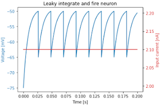
Here's a plot of a 2000-step simulation for a single neuron:

Plot for a single neuron


The speedups using Python, Jax and the JAX jit compiler are dramatic.

Pure Python can simulate a single step for a single neuron in roughly 0.25 µs. so 1,000,000 neurons would take about 0.25 seconds.

numpy can simulate a single step for 1,000,000 neurons in 13.7 ms.

Python, JAX + JAX's jit compilation can simulate a single step for 1,000,000 neurons in 75 µs.

Here's the core code for each version.

# Pure Python
def step(v, tr, injected_current):
    spiking = False
    if tr > 0:
        next_v = reset_voltage
        tr = tr - 1
    elif v > threshold:
        next_v = reset_voltage
        tr = int(refactory_period / dt)
        spiking = True
    else:
        dv = ((resting_potential - v) + (injected_current * membrane_resistance)) * (dt / tau_m)
        next_v = v + dv
    return next_v, tr, spiking
    
# numpy
import numpy as np

def initial_state(count):
    potentials = np.full(count, initial_potential)
    ts = np.zeros(count)
    injected_currents = na * (np.array(range(count)) + 1)
    return injected_currents, potentials, ts


def step(v, tr, injected_current):
    rv = np.full_like(v, reset_voltage)
    dv = ((resting_potential - v) + (injected_current * membrane_resistance)) * (dt / tau_m)
    spikes = v > threshold
    next_v = np.where(spikes, rv, v + dv)
    refactory = tr > 0
    next_v = np.where(refactory, rv, next_v)
    next_tr = np.where(refactory, tr - 1, tr)
    R_DUR = int(refactory_period / dt)
    next_tr = np.where(spikes, R_DUR, next_tr)
    return next_v, next_tr, spikes

# JAX (the only difference from numpy is the import)
import jax.numpy as np


def initial_state(count):
    potentials = np.full(count, initial_potential)
    ts = np.zeros(count)
    injected_currents = na * (np.array(range(count)) + 1)
    return injected_currents, potentials, ts


def step(v, tr, injected_current):
    rv = np.full_like(v, reset_voltage)
    dv = ((resting_potential - v) + (injected_current * membrane_resistance)) * (dt / tau_m)
    spikes = v > threshold
    next_v = np.where(spikes, rv, v + dv)
    refactory = tr > 0
    next_v = np.where(refactory, rv, next_v)
    next_tr = np.where(refactory, tr - 1, tr)
    next_tr = np.where(spikes, R_DUR, next_tr)
    return next_v, next_tr, spikes
    
# JAX jitting
from jax import jit

jstep = jit(step)

Jupyter Notebooks containing the full code can be found at https://github.com/romilly/spiking-jax

All the timings were run on an Intel® Core™ i5-10400F CPU @ 2.90GHz with 15.6 GiB of RAM and a NVIDIA GeForce RTX 3060/PCIe/SSE2 running Linux Mint 20.2, JAX 0.2.25 and jaxlib 0.1.73 with CUDA 11 and CUDANN 8.2.

I have successfully run the code on a Jetson Nano 4 Gb.

I've added the Nano timings to the GitHub repository.

Related posts:


More updates from @rareblog


Sunday, 28 November 2021

Apologies to commenters!

I've just discovered that comments  on the blog have been queuing up for moderation without my realising it. I was expecting notification when new comments were posted but that hasn't been happening.

I'm now working my way through the backlog. If you've been waiting for a response, I can only apologise.


Saturday, 27 November 2021

JAX and APL

Regular readers will remember that I've been exploring JAX. It's an amazing tool for creating high-performance applications that are written in Python but can run on GPUs and TPUs.

The documentation mentions the importance of thinking in JAX. You need to change your mindset to get the most out of the language, and it's not always easy to do that.

Learning APL could help

APL is still my most productive environment for exploring complex algorithms. I've been using it for  over 50 years. In APL, tensors are first-class objects, and the language handles big data very well indeed.

To write good APL you need to learn to think in terms of composing functions that transform whole arrays.

That's exactly what you need to do in JAX. I've been using JAX to implement models of spiking neural networks, and I've achieved dramatic speed gains using my local GPU. The techniques I used are based on APL patterns I learned decades ago.

Try APL

APL is a wonderful programming language, and these days you'll find great support for beginners.

Dyalog offer free APL licences for non-commercial use, and they run Try APL - a website where you can explore the language from within your browser.

Earlier this month I attended the virtual 2021 Dyalog User Meeting. Much of the content covered work that Dyalog and others have done to make the language easier to learn. As well as TryAPL, Dyalog offer a series of webinars. There's a wiki, a flourishing on-line community, and a super new book called Learning APL by Stefan Kruger. You can it read on-line, download it as a pdf, or execute it as a Jupyter notebook.

Wednesday, 13 October 2021

More fun with Spiking Neural Networks and JAX

I'm currently exploring Spiking Neural Networks.

SNNs (Spiking Neural Networks) try to model the brain more accurately than most of the Artificial Neural Networks used in Deep Learning.

There are some SNN implementations available in TensorFlow and PyTorch but I'm keen to explore them using pure Python. I find that Python code gives me confidence in my understanding.

But there's a problem.

SNNs need a lot of computing power. Even if I use numpy, large-scale simulations can run slowly.
Spike generation - code below

So I'm using JAX.

JAX code runs in a traditional Python environment. JAX has array processing modules that are closely based on numpy's syntax. It also has a JIT (Just-in-time) compiler that lets you transparently deploy your code to GPUs.

Jitting imposes some minor restrictions on your code but it leads to dramatic speed-ups.

JAX and robotics

As I mentioned in an earlier post, you can run JAX on NVIDIA's Jetson family. You get excellent performance on inexpensive hardware with a low power budget.

If, like me,  you're a robotics experimenter, this is very exciting!

A helpful and knowledgeable JAX community

To get the best from JAX you need to think in JAX. I've a head start in that I've been using APL for over five decades. APL, like JAX and numpy, encourages you to think and code functionally, applying your functions uniformly to tensors.

There a lot of JAX skills I still have to master, and yesterday I hit a problem I couldn't solve. I needed to create the outer product of two arrays using the mod function. I know how to do that using APL or numpy but I couldn't see how to do it using JAX.

I asked for help in JAX's GitHub discussion forum, and quickly got a simple, elegant solution. The solution showed me that I'd missed some fundamental aspects of the way that indexing and broadcasting work in numpy and JAX. 

The advice came from Jake Vanderplas - an Astronomer turned Google Researcher who has given some excellent talks about Python in Science, including tips on performance.

Generating input spikes with JAX

You may be interested to see the SNN problem I was trying to solve and the code I ended up with

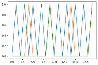
I wanted to generate multiple regular spike trains, with each train having its own periodicity.

I've seen Python code to do that but it's been truly awful: hard to read and slow to execute.

I knew there had to be a simple way to do it.

In APL I'd just do a mod outer product of the periods and a vector of time indices. A zero in the result would indicate that the time was a multiple of the period, so that neuron should fire.

Here's the APL code:

      a ← 1 5 10 ⍝ firing period
      b ← 10 ⍝ time steps
      spikes ← 0 = (1+⍳b) ∘.| a

So far so good, but I could not see how to do the same thing in JAX.

Here's the code in JAX

I'm gradually building up a library of Spiking Neural Network code using Jax. If you're interested, let me know on twitter: @rareblog.


Thursday, 23 September 2021

Installing Jax on the Jetson Nano

Yesterday I got Jax running on a Jetson Nano. There's been some online interest and I promised to describe the installation. I'll cover the process below but first I'll briefly explain

What's Jax, and why do I want it?


tldr: The cool kids have moved from Tensorflow to Jax.
 
If you're interested in AI and Artificial Neural Networks (ANNs) you'll have heard of Google's TensorFlow.

Tensorflow with Keras makes it easy to
  • build an ANNs from standard software components
  • train the network
  • test it and
  • deploy it into production
Even better: TensorFlow can take advantage of a GPU or TPU if they are available, which allows a dramatic speedup of the training process. That's a big deal because training a complex network from scratch might take weeks of computer time.

However, I find it hard to get TensorFlow and its competitors to use novel network architectures.  I am currently exploring types of  network that I can't implement easily in TensorFlow.

I could code them in Python and Numpy but I want to be able to run them fast, and that means using a GPU.

Hence Jax.

You can read about why DeepMind uses Jax here

Jax implements many of Numpy's primitives on a GPU and it can also convert functional, side-effect-free Python code.

It also supports automatic differentiation. I'm not going to be using back propagation in the work I'm doing, so that's not a big deal for me. If you are, you can see online examples that build and train networks from scratch in a few lines of Python code.

I'll give some numbers for the speed-ups you get later in the article. For now, I'll just say that Jax code runs faster than Numpy on the Nano, and faster still when compared with Numpy on the Raspberry Pi.

Jax on the Jetson Nano

Jetson Nano with SSD

There are several ways you can run Jax-based applications; it's not hard to install on a Linux system, and you can run it on Google's wonderful, free Colab service. My interest lies in using neural networks with mobile robots, so I want to run it on an Edge Computing device with GPU hardware built-in.

The Jetson Nano is ideal for that.

I recently came across an article on NVIDIA's developer website that described how to install Jax on the Nano. It included a warning that the installation was slow and required a large (10GB) swap file.

I decided to re-configure one of my Nanos from scratch and set it up to boot from a USB SSD. I did the whole process in three stages using links which I have listed below, along with the gotcha I hit and my work-around.

  1. I set up the Nano in headless mode using an SD card.
  2. I configured the Nano to boot from a USB SSD.
  3. I installed Jax from source.

Set up the Nano in headless mode using an SD card


NVIDIA have really simplified the setup process since I started exploring the Nano a couple of years ago.

The NVIDIA Getting Started guide now gives two ways to set up your Nano.

One requires an HDMI screen, a mouse and keyboard. 

The other needs an Ethernet connection, a suitable power supply and a jumper to configure the Nano to power itself from its barrel connector rather than from USB.

I want to run my Nano in fast, full-power mode and I have very limited desk space. I decided to go for a Headless Setup. I followed these three steps in the NVIDIA guide:

  1. Prepare for Setup*
  2. Write Image to the microSD Card
  3. Setup and First Boot**
* There are alternative power supplies to the Adafruit supply that NVIDIA mentioned. I purchased this one in the UK.

** Make sure you scroll down to the section Initial Setup Headless Mode

Configure the Nano to boot from USB SDD


I followed this excellent guide from JetsonHacks.

I found that the Nano did not boot from the SSD first time but it's booted reliably ever since.

Installing Jax from source

I followed the process given in this post on the NVIDIA developer website. I hit one snag, which was easy to solve: After I had set up a Python 3.9 virtual environment, I needed to run

sudo apt install python3.9-distutils

before I could run the stages that used pip.

First time through I failed to realise that the heading How to Add Swap Space on Ubuntu 18.04 is actually a link to a web page that tells you how to do that. I also set the swap file size to 16 GB rather than 10GB as recommended.

The installation guide says that the compilation process takes 12 hours. Mine took about 6 hours, possibly because I was running the Nano in Max Power mode.

Once the compilation process has finished, the remaining steps take a minute or less!

First Timing Tests

It looks as if Jax is six to seven times faster than numpy on the Nano when dot-multiplying a 4000x4000 element matrix with itself, and 25 times faster than a Pi 4 running numpy. That's worth the effort of installation :)


Monday, 15 March 2021

MicroPlot on the PyPortal - progress and frustration

Update: I got a fix within minutes of posing the problem on the Adafruit discord channel!

Here's the correct bitmap:

The problem is now solved,

MicroPlot now runs well on the Adafruit PyPortal and  Clue as well as the Pimoroni Pico Explorer base, but I've been tearing my hair out trying to solve a problem saving bitmaps.

The bitmap problem

Here's a screenshot of a display on the PyPortal together with the bitmap file which should show what's on the screen. I could not work out what's going wrong.

The code creates the plot and then uses the screenshot code that Adafruit provides.

import math from plotter import Plotter from plots import LinePlot import board import digitalio import busio import adafruit_sdcard import storage from adafruit_bitmapsaver import save_pixels def plot(): sines = list(math.sin(math.radians(x)) for x in range(0, 361, 4)) lineplot = LinePlot([sines],'MicroPlot line') plotter = Plotter() lineplot.plot(plotter) def save(): spi = busio.SPI(board.SCK, MOSI=board.MOSI, MISO=board.MISO) cs = digitalio.DigitalInOut(board.SD_CS) sdcard = adafruit_sdcard.SDCard(spi, cs) vfs = storage.VfsFat(sdcard) storage.mount(vfs, "/sd") save_pixels("/sd/screenshot.bmp") plot() save() print('done')

What works, what doesn't?

When I first wrote about MicroPlot it ran on the Pico. The code worked but I knew it would need refactoring as I extended it to cover other plot types and other devices.

Past experience has taught me the value of automated tests for embedded projects. I wondered if I could capture MicroPlot's output in bitmap files and use them in tests. I didn't know much about the format of Bitmap files so I started to look for code I could borrow and adapt.

I soon discovered that bitmap files could use different ways of encoding colour, and the simplest, smallest format created monochrome bitmaps.  I soon got a Bitmap file-saver working reliably on the Pico. As you can see, it works, and you can find the code in the MicroPlot project on GitHub.

Soon after that I discovered some Adafruit colour bitmap saver code and adapted it to run on the Pico. As you can see, it too worked well.

But...

When I ran the unmodified Adafruit code on the PyPortal, it scrambled the image, as shown earlier.

I've checked that I am using the latest production versions of the Adafruit code. Can anyone suggest what I'm doing wrong? The code (mine and Adafruit's) looks sensible, but it seems to corrupt every screenshot  bitmap that I try to take.

If you can spot the problem, let me know in the comments, tweet to @rareblog or respond to my cry for help on Discord.


Friday, 26 February 2021

More Raspberry Pi Pico experiments

If you're exploring the Raspberry Pi pico, here are some more resources

MicroPlot

I've started a new project called MicroPlot. It's been developed on the Pico though it will eventually work on other  micro-controllers and computers. It's a minimal plotting package and it already has enough functionality to be useful.

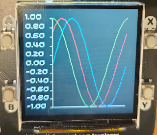
It will plot simple line plots; the first example below is a series if sine waves and the second shows the voltage across a capacitor as it charges and discharges.

Plotting Sine waves

Capacitor charging and discharging


MicroPlot has its own project on GitHub. You can read about it and download the code at https://github.com/romilly/microplot and I will be soon be using it for some more electronics experiments.

Using the UART

The current MicroPython documenation for the Raspberry Pi Pico is a bit thin on detail about using the UART. I've added a short example in my pico-code project on GitHub.

The Tiny2040 is available from Pimoroni!

Pimoroni Tiny2040


I was lucky enough to get an early pre-production version of the Pimoroni Tiny2040.

It's now available in the Pimoroni shop.

You'll find a couple of simple examples in my pico-code project. They are in the
 src/pico_code/pico/tiny2040/ 
directory.

Resistomatic

Over the years I've blogged about a number of implementations of resistomatic, a home-made resistance meter. Most of them use an 8-bit ADC which complicates the design because 8 bits give a low resolution. The pico's ADCs are 12-bit. My crude design just needs a bridge that compares the voltages across the reustor to be measured and a know 1K ohm resistor. It's accurate enough (5%) for my purposes across a range of resistance. I've checked it with resistors ranging from 56R to 100K ohms.

You'll find the code and little more information at https://github.com/romilly/pico-code/blob/master/docs/resistomatic.md


More on the way

I've several more Pico projects in the pipeline. To stay up-to-date as I release them, follow @rareblog on twitter.


set up a new GitHub

Saturday, 13 February 2021

MicroPython development on the Raspberry Pi Pico

Get Started with MicroPython on Raspberry Pi Pico suggests that you use the Thonny editor for development.

Thonny will get you off to a quick start, but you may have an alternative editor you'd prefer to use.

Lots of my friends now use VS Code; some are vim or emacs experts; many, like me, use PyCharm as their normal Python development environment.

I find it more comfortable to use my normal editor for MicroPython development, but I have more compelling reasons.

The first is refactoring support. I'm learning as I go, and I often want to improve the design of my code libraries as I come to understand things better. PyCharm does a very good job of refactoring Python code.

There's another issue to do with version control.

I'm currently sharing my Pico code on GitHub. That means I need to keep code on the Pico in sync with the code on my workstation. I haven't found an easy way to do that with Thonny, so I am using another tool to move and test code.

rshell was my first choice, but I've had some problems with it, as have others.  Les Pounder (@biglesp) came to my rescue. He has a really useful series of blog posts called Tooling Tuesday.

A while ago Les recommended Adafruit's ampy for use with MicroPython boards. Ampy works really well with the Pico. I now have it on my workstation, and on a Raspberry Pi which I also use for Pico development.

Les also recommends tio for serial communications. tio is a serial terminal program. Its great advantage over others is that it will try to reconnect automatically if the serial link goes down. tio is available on the Pi but I couldn't find it in the official repositories for my very backdated Linux Mint installation. Fortunately it took just three minutes to download tio and build it from source, following the instructions on its GitHub page.

I'll soon be publishing more Pico and Tiny2040 code. If you want to stay up to date, follow me (@rareblog) on twitter.


Friday, 12 February 2021

Raspberry Pi Pico project 2 - MCP3008

This post show you how to drive the MCP3008 8-channel ADC using a Raspberry Pi Pico. I'll start with a personally embarrassing and annoyingly relevant story. I'll also tell you about a minor 'gotcha' when using SPI on the Pico, and how you can avoid it. Finally, I've include the code and fritzing diagram I used to test the interface.

First, the story.

Back in 2012, when the Raspberry Pi was fresh and new, I was running a startup called Quick2Wire.  We made add-on boards for the Pi. Just before Christmas we sent out our first batch of boards to a small army of beta-testers.

The beta boards didn't work.


Somehow a single trace on the pcb had got deleted and one of the GPIO pins was isolated. The boards were still usable and it wasn't too hard to solder in a jumper wire to replace the missing trace, but it was very embarrassing.

It wasn't just that we'd shipped boards with a defect. The really annoying thing was that I'd set up an  automated loop-back test harness, but in a fit of over-confidence I just did a quick manual test on the board before we sent them out.

The automated test would have caught the problem which my quick manual test failed to spot.

I'll come back to loop-back testing below.

Back to the Pico

One of my goals for my Pico mini-projects was to verify that I could drive I2C and SPI chips using the Pico's MicroPython. I2C and SPI protocols are really useful.They let you drive all kinds of interesting sensors and actuators, and that means that they enable lots and lots of interesting applications.

There are an SPI example in the excellent Getting Started guide, and it gave me some useful ideas. There's a little more information in the Pico Python SDK documentation, and yet more clues in the Pico pinout diagram. I also found a CircuitPython driver for the MCP3008 on Adafruit's GitHub repository.

I reckoned that I now had enough information to wire up and drive an MCP3008 chip. The MCP3008 is an 8-channel  ADC (analogue-to-digital) converter. The Pico has 3 ADC pins, but sometimes you need more. The 3008 has a simple, well documented SPI interface, and I had a few in my parts bin, so it was an obvious choice for the test.

I quickly wrote some code, and sure enough it worked. I posted it as a gist on GitHub and tweeted about it.

Some time later that day I got a comment from Matt Trentini, one of the members of  a Facebook group that covers the Pico and other MicroPython controllers. He suggested a small refactoring to the code. It clearly made the code better, and I decided to implement it.

Loopback tests

Some people are smart enough to be able to refactor code without tests but I am not one of them.

I decided to create a loop-back test. In a loop-back test the UUT (unit under test) provides an output which is connected to one of its inputs. In other words, the output is looped back  to the input. When you change the output, the input should change. If everything works as expected, the loop-back test passes.

In this case, I just connect a GPIO pin to one of the MCP3008 inputs. When the GPIO output is high the MCP3008 should read 3.3 volts; when it's low, the MCP3008 should read 0 volts.
I set up a loop-back test and ran it. It worked.

I did the refactoring and the test stopped working.

What had I done wrong?

SPI defaults on the PICO


The Pico has two hardware SPI busses, and you can access each buss from several different pins. An SPI chip needs three data inputs and one chip selection input. The data inputs are traditionally called SCK, MISO and MOSI. SCK carries a clock signal. MISO carries data from the chip to the Pico, and MSOI carries data from the Pico to the chip. Because the Pico can be a controller or be controlled by SPI,  the Pico's pinout diagram calls MISO  SPI RX and calls MOSI  SPI TX.

The Pinout diagram covers both SPI busses, and the example in the Getting Started book shows an example that uses Pin 2 as SCK, Pin 3 as TX and Pin 4 as RX.

I wrongly assumed that those were the default pins. In the first bit of code I specified the pins explicitly. In the refactored code, I used the default SPI constructor.

After hours of puzzlement I discovered from the Pico Python SDK documentation that the default pins are 6, 7 and 4, not 2, 3 and 4 as used in the book example. It was easier to change my code than to change my wiring, so the code on GitHub now specifies the pins explicitly.

Here's the code for the MCP3008 class.
"""
MicroPython Library for MCP3008 8-channel ADC with SPI

Datasheet for the MCP3008: https://www.microchip.com/datasheet/MCP3008

This code makes much use of Adafruit's CircuitPython code at
https://github.com/adafruit/Adafruit_CircuitPython_MCP3xxx
adapted for MicroPython.

Tested on the Raspberry Pi Pico.

Thanks, @Raspberry_Pi and @Adafruit, for all you've given us!
"""

import machine


class MCP3008:

    def __init__(self, spi, cs, ref_voltage=3.3):
        """
        Create MCP3008 instance

        Args:
            spi: configured SPI bus
            cs:  pin to use for chip select
            ref_voltage: r
        """
        self.cs = cs
        self.cs.value(1) # ncs on
        self._spi = spi
        self._out_buf = bytearray(3)
        self._out_buf[0] = 0x01
        self._in_buf = bytearray(3)
        self._ref_voltage = ref_voltage

    def reference_voltage(self) -> float:
        """Returns the MCP3xxx's reference voltage as a float."""
        return self._ref_voltage

    def read(self, pin, is_differential=False):
        """
        read a voltage or voltage difference using the MCP3008.

        Args:
            pin: the pin to use
            is_differential: if true, return the potential difference between two pins,


        Returns:
            voltage in range [0, 1023] where 1023 = VREF (3V3)

        """

        self.cs.value(0) # select
        self._out_buf[1] = ((not is_differential) << 7) | (pin << 4)
        self._spi.write_readinto(self._out_buf, self._in_buf)
        self.cs.value(1) # turn off
        return ((self._in_buf[1] & 0x03) << 8) | self._in_buf[2]

And here's the code for the loop-back test.
from machine import Pin, SPI
from time import sleep, sleep_ms
from mcp3008 import MCP3008

spi = SPI(0, sck=Pin(2),mosi=Pin(3),miso=Pin(4), baudrate=100000)
cs = Pin(22, Pin.OUT)
cs.value(1) # disable chip at start

square = Pin(21, Pin.OUT)

chip = MCP3008(spi, cs)

while True:
    square.value(1)
    actual = chip.read(0)
    print(actual)
    sleep(0.5)
    square.value(0)
    actual = chip.read(0)
    print(actual)
    sleep(0.5)

Finally, here's the fritzing diagram for the loopback wiring.


I've several more mini-projects to cover in the next day or so. If you want to keep track of what I'm up to, follow me (@rareblog) on twitter.


Raspberry Pi Pico - simple projects

Introducing fungen - an AF function generator.

Lots of pioneers are now creating tutorials and sample projects for the Raspberry Pi Pico and the Pimoroni Tiny2040.

One of my first mini-projects is fungen - a Pico-based AF (audio frequency) function generator that uses the Pico's PIO (programmable I/O) to generate a waveform.

The Pico's head start


The Pico was announced just a few days ago. It arrived out of the blue complete with lots of interesting add-ons available, and with excellent documentation.

The reference documentation is full of useful examples, including several that take advantage of the Pico's powerful PIO. PIO allows users to set up custom input-output capability, and one of the examples shows how to use PIO to implement PWM (Pulse width modulation).

The Pico already has plenty of PWM-capable pins, but I wondered if I could hack the PWM code to turn the Pico into a simple signal generator.

Indeed you can, and that's how fungen works.

I made a couple of minor changes to the  PIO PWM sample code and wrote a short program on my workstation that generated the values I needed to to generate a sine wave. Next I wired up a very simple low-pass fiter from a capacitor and resistor. I fired up my BitScope micro USB-based oscilloscope, loaded my code onto the Pico using the thonny editor, and took a look at the output.

It worked!


Of course a useful signal generator lets you vary the frequency of its output. That's usually done using a knob that turns a potentiometer. Could I use that with the Pico?

I worried that the reading of the voltage would interrupt the process of generating the sine wave. I quickly realised that the Pico has a multi-core. Could I use the second code to read the pot?

I couldn't find a micropython example of multi-threaded code for the Pico, but Ben Everard quickly came to my rescue. He's written some code that uses both cores, and it turns out to be really easy.


Multi-threading on the Pico


Here's the current code for  the function generator.
# Example of using PIO for function generation using hacked PWM example

from machine import ADC
from time import sleep_us, sleep_ms
import _thread

from pio_dac import PIOPWM

# Pin GP22 is output
pwm = PIOPWM(0, 22, max_count=250, count_freq=10_000_000)

sines = [
    124, 127, 130, 133, 136, 139, 142, 145, 148, 152,
    155, 158, 161, 164, 167, 170, 172, 175, 178, 181,
    184, 186, 189, 192, 194, 197, 200, 202, 204, 207,
    209, 211, 214, 216, 218, 220, 222, 224, 226, 227,
    229, 231, 232, 234, 235, 237, 238, 239, 240, 241,
    242, 243, 244, 245, 246, 246, 247, 247, 248, 248,
    248, 248, 249, 249, 248, 248, 248, 248, 247, 247,
    246, 246, 245, 244, 243, 242, 241, 240, 239, 238,
    237, 235, 234, 232, 231, 229, 227, 226, 224, 222,
    220, 218, 216, 214, 211, 209, 207, 204, 202, 200,
    197, 194, 192, 189, 186, 184, 181, 178, 175, 172,
    170, 167, 164, 161, 158, 155, 152, 148, 145, 142,
    139, 136, 133, 130, 127, 124, 120, 117, 114, 111,
    108, 105, 102, 99, 95, 92, 89, 86, 83, 80,
    77, 75, 72, 69, 66, 63, 61, 58, 55, 53,
    50, 48, 45, 43, 40, 38, 36, 33, 31, 29,
    27, 25, 23, 21, 20, 18, 16, 15, 13, 12,
    10, 9, 8, 7, 6, 5, 4, 3, 2, 1,
    1, 0, 0, -1, -1, -1, -1, -1, -1, -1,
    -1, -1, -1, 0, 0, 1, 1, 2, 3, 4,
    5, 6, 7, 8, 9, 10, 12, 13, 15, 16,
    18, 20, 21, 23, 25, 27, 29, 31, 33, 36,
    38, 40, 43, 45, 48, 50, 53, 55, 58, 61,
    63, 66, 69, 72, 75, 77, 80, 83, 86, 89,
    92, 95, 99, 102, 105, 108, 111, 114, 117, 120,
]


pot = ADC(26)
delay = [400]


def read_pot():
    while True:
        v = pot.read_u16()
        delay[0] = 20 + (400 * v)// 65000
        sleep_ms(100)


_thread.start_new_thread(read_pot, ())

while True:
    for i in range(0, 250, 25):
        pwm.set(sines[i])
        sleep_us(delay[0])

It uses pio-dac.py which is the hacked version of the PWM example. You'll find all the code (and some other examples) on GitHub.

I'll blog about more of the examples over the next few days. If you want to keep track of what I'm up to, follow me (@rareblog) on twitter.

Saturday, 30 January 2021

Pi Pico emulating an Etch-a-sketch


One Christmas, long, long ago, someone gave me an Etch-a-sketch.

I was a bit of a klutz then (indeed, I still am). I never produced great works of art, but the Etch-a-sketch was a lot of fun to play with.

Yesterday I wondered how easy it would be to emulate an Etch-a-sketch using the Raspberry Pi Pico.

I’d just finished yesterday’s article about how to link a host to the Pico using PySerial.

Why not

  • get the Pico to print out how far two potentiometer knobs were turned, 
  • read the output on the Pi using PySerial, 
  • and use the Turtle package on the Pi to create the display?

It sounded too simple to work, so I started coding with some trepidation.

The first job was to connect a couple of potentiometers to the analogue inputs of the Pico.

After that I wrote a short MicroPython program which read the analogue values and printed them out.

Here it is:

import machine
import utime

pot_l = machine.ADC(27)
pot_r = machine.ADC(26)


def run():
    while True:
        print(pot_l.read_u16(), pot_r.read_u16())
        utime.sleep_ms(100)

run()

I installed the program on the Pico and checked that the output changed when I rotated the knobs.

Next I wrote another short Python program on the Raspberry Pi. It uses sender.py, described in yesterday’s article.

Here’s the code:

from sender import Sender
import turtle

s = Sender()
scr = turtle.getscreen()
t = turtle.Turtle()


def convert(text):
    return (int(text)-200)//300


while True:
    text = s.receive()
    x,y = [convert(text) for text in  text.split()]
    t.setx(x)
    t.sety(y)

It worked!

I used a Pimoroni Explorer base for the version in the photo at the top, but you can use a Pico with a standard breadboard. Here's the Fritzing diagram.


Here’s some output, confirming that my coding is better than it was when I was young, but my drawing ability isn’t :)

My next task is to adapt the code to create a very simple audio frequency oscilloscope. I’ll write that up next week.

To keep up to date with this series follow @rareblog on twitter.

Friday, 29 January 2021

Controlling a Raspberry Pi Pico remotely using PySerial

Update: I'm using thie code below in another project, and found that I had not correctly fixed the reported bug. The new version passes automated tests, and I am pretty sure it works OK.

I have changed the name of the class to Talker since it can both send and receive information.

Apologies to all concerned for the bug!

Introduction

You can use a Raspberry Pi Pico as a powerful peripheral to a host - a Raspberry Pi, a Jetson Nano, a laptop or workstation. In this article you'll see how to interact with a Pico running MicroPython or CircuitPython by writing some Python code that runs on the host.

The software is easy to use. It enables you to send a Python statement to the Pico and read the results. The statement can be any valid MicroPython code.

Setting up the host and the Pico

For this article I've used a Raspberry Pi as the host, but any computer running Windows, Linux or Mac OS will do so long as it has Python 3.5 or later installed.

In particular, you can use this technique to connect a Raspberry Pi Pico to a Jetson Nano host or any other member of the Jetson family.

The host needs to have the serial package available, so you need to run 

pip3 install PySerial

on the host.

You'll need to install MicroPython on the Pico. You'll find instructions for MicroPython installation in the official Getting Started Guide which I reviewed recently.

 The £10 Guide is worth buying, but if you can't wait for your copy to arrive you can download a free pdf.

The guide will also tell you how to use the Thonny editor to install the necessary code on your Pico.

Connect the host and the Pico

First, connect the host to the Pico using a USB data lead. Some USB leads only supply power. They will not work.

Install software on the Pico

Next, install the blinker script.

The blinker.py script runs on the Pico, but you should rename it to main.py. Here's the code:

"""
Example for remote control from host via Serial link.

This is the code to run on the Pico.
It sets up the onboard LED and allows you to turn it on or off.
"""
from machine import Pin

# use onboard LED which is controlled by Pin 25
# on a Pico W the onboad lLED is accessed differently,
# so commeent out the line below
# and uncomment the line below that
led = Pin(25, Pin.OUT) # veresion for Pico
# led = Pin('LED', Pin.OUT) # version for Pico W


# Turn the LED on
def on():
    led.value(1)

# Turn the LED off
def off():
    led.value(0)
Install it on the Pico using the Thonny editor.
  1. Open the gist on GitHub.
  2. Copy the code to your clipboard.
  3. Open Thonny and make sure it has connected to the Pico.
  4. Paste the code into the Thonny editor window.
  5. Save it on the Pico as main.py.
  6. Close the Thonny editor.

If you leave the Thonny editor open it will keep the serial port open on the host, and the serial program below will not work!

Since you saved the program as main.py it will run on the Pico automatically.

The talker.py script runs on the host. It uses PySerial to send commands from the host to the Raspberry Pi Pico and read the result.

Here's the talker code:

import serial


class Talker:
TERMINATOR = '\r'.encode('UTF8')

def __init__(self, timeout=1):
self.serial = serial.Serial('/dev/ttyACM0', 115200, timeout=timeout)

def send(self, text: str):
line = '%s\r\f' % text
self.serial.write(line.encode('utf-8'))
reply = self.receive()
reply = reply.replace('>>> ','') # lines after first will be prefixed by a propmt
if reply != text: # the line should be echoed, so the result should match
raise ValueError('expected %s got %s' % (text, reply))

def receive(self) -> str:
line = self.serial.read_until(self.TERMINATOR)
return line.decode('UTF8').strip()

def close(self):
self.serial.close()


On the host

  1. Copy talker.py from this github gist into an editor and save it in a directory of your choice.
  2. In that directory, run python3 to start an interactive session.
  3. Type from talker import Talker
  4. Type t = Talker(). If you are running on Windows, you will need to type t = Talker('COM6') replacing COM6 by whatever port the Pico is visible on.
  5. Type t.send('2 + 2')
  6. Type t.receive(). If all is well, this will print the result 4.
  7. Type t.send('on()')     #  The on-board LED on the Pico should turn on.
  8. Type t.send('off()')    #  The on-board LED on the Pico should turn off.
  9. When you have finished, type t.close().

Of course in a real application you'd normally create the sender, send and receive data using a Python script. In a future post I'll show how to do that to create a simple weather station with the Pico and plot the temperature and light level on the host. Before that I'll explore other ways of connecting and controlling the Pico from a Host.

To keep up to date with this series follow @rareblog on twitter.


Wednesday, 27 January 2021

Which Python should you install on your Raspberry Pi Pico?

 The new Raspberry Pi Pico sold out soon after launch. One of the reasons it's so popular is that you can program it in Python.

There are two versions of Python to consider: MicroPython and CircuitPython. Fortunately they are very easy to install or replace and they are very similar. Let's compare them so you can decide which to use.

The Official guide to the Pico (reviewed here)recommends that you install the official version of MicroPython. MicroPython has been around since 2014, and it's been ported to quite a few boards. It was  created by Damien George, and he is responsible for the port to the Pico.

If you're starting with MicroPython and  want to work your way through the Official Guide, use the official version.

If you've been using MicroPython for a while you've probably heard of CircuitPython. It's based on MicroPython but  adapted by the inventive folk at Adafruit. 

CircuitPython lets you run the same program on any supported board without having to change it. If you use the Adafruit add-ons (or any of the other compatible products) you can use the same code to drive them on any CircuitPython-enabled board. 

Adafruit even have software called Blinka which lets you run the same code on a Raspberry Pi or  Jetson Nano!

CircuitPython makes it easy to move your code from one environment to another, and it supports a huge range of add-on devices from Adafruit and other vendors. At present, though, the Pico version is in beta-test and some features have not been implemented. I'm experimenting with it but I'd advise most Pico users to stick with the official version for now.

In the Pico posts I have planned, most of my code will run on both versions without change. I may occasionally write code that relies on some of the CircuitPython extensions. I'll make it clear when I do!

The next blog post will cover using PySerial to drive a Pico form a Host Computer. The Pico can be running MicroPython or CircuitPython.

To keep up to date with this series follow @rareblog on twitter.

Tuesday, 26 January 2021

Five ways to connect Raspberry Pi and Pico

The Raspberry Pi and Pico are each very capable, but sometimes you'll want to connect them together.

For example, if you're building a robot you may want to use the Pi for computer vision, while relying on the Pico for predictable response times. 

How can you get the Pi and the Pico to talk to each other?

There are several possibilities, each with their own characteristics.

  1. You can connect them with a USB lead and use Thonny to talk to the Pico. That's very easy; it just uses the MicroPython REPL to control the Pico, bit it's very limited. If you've used the REPL to turn the Pico's on-board LED on and off, you've use this option already.
  2. You can connect the Pi to the Pico via USB and use a library called PySerial to send and receive data using a Python program that you write. That's a bit harder but much more flexible.
  3. You can connect the Pi and the Pico using their TTL serial interfaces - possible in theory, though I can't see much reason to do things that way.
  4. You can connect them using a programs that use a protocol called SPI. That's likely to be useful if the Pi needs to talk to a couple of Picos.
  5. You can connect them using a protocol called I2C. That would allow the Pi to talk to lots of Picos, but it's probably the trickiest option, for reasons I'll explain.
In the next post I'll focus on option two. I'll cover SPI and I2C in later posts.


Monday, 25 January 2021

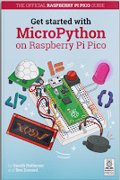
Review: Get started with MicroPython on Raspberry Pi Pico

If you want to explore the Raspberry Pi Pico you'll find it really easy to get started.

On the day of the announcement the Raspberry Pi  Foundation released excellent documentation.The Raspberry Pi press also published a great starter guide: Get started with MicroPython on Raspberry Pi Pico.

It's a super book. The authors are professional journalists and experienced Pi enthusiasts, and it shows!

The book covers everything a beginner needs to know to start exploring Physical Computing with the Pico.

A guided tour of the Pico

Chapter 1 starts with a guided tour of the board.

Next it explains how to solder the headers you'll need if you want to use the Pico with a breadboard. The soldering instructions are clear enough for a novice to follow. The book wisely warns younger users to make sure they are supervised by an adult. It's easy to burn yourself badly with a hot iron while you're learning.

The chapter finishes with clear instructions that tell you how to install MicroPython on the Pico.

Chapter 2: Hello Pico World!

Chapter 2 gets you running your first programs.

The book recommends using the Thonny IDE. As I mentioned in yesterday's blog post, I hit a minor snag with Thonny; it claims to run under Python 3.5, but it won't, as it uses language features that version 3.5 won't support. That's not a problem if you are using a Raspberry Pi with current software.

You will need to make sure that the version of Thonny is up to date (3.3.3 or later). I had to upgrade the software on my Pi to get access to the MicroPython (Rapsberry Pi Pico) option.

You'll probably find the first couple of program rather familiar.

The first is a minimalist version of Hello World.

Since Thonny includes a REPL, you can enter print("Hello, World!") and see an immediate response.

After introducing the idea of looping in Python, and exploring conditional statements, the book moves on to Physical computing: connecting your Pico to the surrounding world using electronic components.

Chapter 3: A whirlwind tour of electronics

You'll find out about all the Pico's GPIO pins and what you can do with them. Old hands will be delighted to discover that the Pico can read analogue signals. Three of its pins are connected to 12-bit ADC channels, so you can measure up to three voltages. Chapter 3 also explains how to use a breadboard with jump wires, and introduces a range of electronic components:

  • push buttons
  • LEDs
  • Resistors
  • Buzzers
  • Potentiometers
  • PIR sensors and
  • I2C LCD Screens.

Chapter 4: blinkenlights at last!

Chapter 4 ups the pace. You'll learn about connecting components to the Pico and controlling them using MicroPython. The very first program needs no extra components, since the Pico has an onboard LED. 


There's lots more to come, but you'll need some extra components for the remaining experiments. The book has a shopping list and all of the components should be easy to find. First you'll control an external LED with its load resistor. After that you'll add a push-button and use that to control your LED.

Chapters 5-9

Chapters 5 to 9 walk you through a series of projects that will introduce you to many of the capabilities of the Pico:

  • Traffic Light Controller
  • Reaction Game
  • Burglar Alarm
  • Temperature Gauge
  • Data logger

Chapter 10: I2C and SPI


Image courtesy of Pimoroni
Chapter 10 covers two of my favourite topics: I2C and SPI. The I2C and SPI protocols make it possible for the Pico to drive LCD displays, as well as controlling servos, motors and other useful components.

Pimoroni offer an Explorer base for the Pico, and it has an on-board LCD. The image  shows a display driven by the Pico which has enough processing power to show animated images!

Pico PIO - an end to bit-banging!

The book concludes with three appendices. Appendix A covers the Pico specification. Appendix B covers the Pico pinout. Appendix C - the last one - covers one of the most exciting features of the Pico - PIO.

As well as its dual-core Arm CPU the Pico has eight tiny PIO computers than you can program and use to control GPIO pins. Not everyone will need them, but they have lots of interesting potential. If you need to use a protocol that's not already supported you have two options.

You can write code to do it, using the main CPU. That's known as bit-banging, and it suffers from a couple of problems; it needs quite a bit of processing power, and it's prone to timing errors.

Your second option uses those extra PIO processors.

Appendix C gives you a quick guided tour with examples to try and then adapt. I'm hoping to use PIOs to implement a couple of useful protocols: Dallas Semiconductor's one-wire protocol, and the DMX protocol used in theatres and discos to control lighting systems. I'll report in due course!

Summary

I love this book. It's clear, beginner-friendly, and beautifully illustrated.

At £10 it's not expensive, and the profit will help the Raspberry Pi foundation in its work. If you really can't afford a printed copy you can download a free pdf version. I have both.

If you're getting a Pico, or wondering whether to, start by getting this book!

I've lots more to share as I explore the Pico. Follow @rareblog on twitter to keep up to date!


Sunday, 24 January 2021

Getting started with the Raspberry Pi pico

I'm always excited when Eben Upton pulls another Raspberry Pi rabbit out of his capacious topper.

Last week he announced the $4 Raspberry Pi pico. It's a unique product for several reasons, and I put an order in as soon as I saw the announcement.

It's easy to get the pico going

The pico's on-line documentation is superb and it's supplemented by an excellent and inexpensive book from Gareth Halfacree and Ben Everard.

I did hit one minor 'gotcha'. I've been working on my main workstation which runs Linux Mint, and discovered the hard way that the Thonny Editor won't install properly if you're using Python 3.5

Python 3.5 has reached end-of-life, but it's still the default on Linux Mint 18.3. If I want to use a later version I have to set up a virtual environment. Once I did that, Thonny installed perfectly and within a couple of minutes I'd created a Hello World script and run it on the pico.

If you're using a Raspberry Pi to program the pico you won't have this problem, as the current version of Raspberry Pi OS has Python 3.7 installed.

Raspberry Pi partners with Pimoroni, Adafruit, sparkfun and Arduino

I mentioned that the pico was unique for several reasons. One I find particularly exciting: the RP2040 chip at the heart of the pico will be used in products from Pimoroni, Adafruit, sparkfun and Arduino as well as the Raspberry Pi Foundation.

It's great to see these movers and shakers cooperating in this way. It makes good commercial sense. This cooperation will create more opportunities for us all, and will expand the market as a result.

I'll be documenting my pico exploration as I go. Follow @rareblog on twitter if you want to stay informed.

Tuesday, 12 January 2021

Tom Gilb on Systems Enterprise Architecture

A few days ago my friend Tom Gilb asked me to comment on his new book on SEA (Systems Enterprise Architecture).

I've followed Tom's work since he wrote an inspirational and iconoclastic column in Computer Weekly back in the 1980s. 

Tom has always been sceptical of claims made in IT without quantified evidence. Early in SEA he tells us 'There comes a threshold of complexity in all disciplines where quantification becomes a necessary tool. The time has come for IT Enterprise Architecture to really make use of quantification, and not just talk about doing it.'

He's right, and many traditional IT departments need to mend their ways, but I think Tom underestimates the extent to which the Smart Kids already practice what he preaches. They know that gives them a competitive edge, and for that reason they tend not to broadcast what they do. I'm lucky enough to know a few of them, so I get to hear a little of what they are up to and how they do it.

The TDD world has always placed a lot of emphasis on verifying functional correctness through automated testing. Tom has always placed additional emphasis on the (non-functional) qualities of software: reliability, usability, performance, security and so forth. These are vital to the delivery of business value but they need much more skill to quantify and test. That's why most requirements documents have paid lip service to the qualities without specifying quantified goals and the means of measurement.

While traditional IT often fails in that respect, most young, successful cloud-based businesses live or die by the efficiency, availability, usability, and reliability of their software. They measure these qualities in real-time and deploy changes in real-time to fix problems when they detect them. I'm sure they could do better, and I'm sure that Tom's book could help them to do that, but they are already way ahead of traditional IT.

Tom's expertise can help those who are already doing the right things; for others, his approach would be a game-changer. Sadly I fear few will take advantage of it. They would have to change from being an expert in the old ways to being a novice in the new, and that's always a difficult thing to do.

If you'd like to take a look at the SEA book, you can download a free PDF here:

https://www.dropbox.com/sh/1t8uwy9xxu52tl5/AACYDtWQ0EDCTZ6D-pJIaSM4a?dl=0