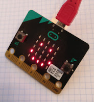
MonkMakes is the Hardware business started by Simon and Linda Monk to complement Simon's many excellent maker books.
They've just released three new boards for the micro:bit. Today I had a play with their sensor board, which has a light sensor, a microphone and a thermometer.
It's incredibly easy to connect to the micro:bit. I'm clumsy, but I wired it up in a minute at most.
There's sample Python code a little way down on the MonkMakes website page, but WordPress has mangled it a bit; the code wouldn't run until I replaced all the em-dashes with minus signs and replaced all the double quotes. There are also a lot of redundant blank lines, but that's just a cosmetic issue.
Once you've fixed those issues you can use Mu's REPL to display the light level, temperature and sound level at pone second intervals. The microphone seems to be directional. I had loud music on when testing, which didn't register, but it responded well to a clap or a shout.
Over the next few days I hope to try out the Relay board and Loudspeaker. Follow me on twitter if you want to see when the articles are posted.
Saturday, 28 October 2017
Thursday, 12 October 2017
The ClusterHat goes Stereo!
Yesterday I described my first experiments with the Raspberry Pi ClusterHat.
I'vehad a play done a bit more serious research since then and I now have two Pi cam2s connected to two of the Pi zeros. Now I can take stereo photos!
The first pair of images aren't of great artistic merit, but they prove things work.
Morten and I plan to build on this using APL to convolve the two images in order to determine the distance from the cameras of each pixel in the scene. Once the ClusterHat and PiCams are mounted on a mobile base we hope we'll have a mobile robot with stereo depth perception.
Follow progress on @rareblog and @dyalogapl!
I've
The first pair of images aren't of great artistic merit, but they prove things work.
Morten and I plan to build on this using APL to convolve the two images in order to determine the distance from the cameras of each pixel in the scene. Once the ClusterHat and PiCams are mounted on a mobile base we hope we'll have a mobile robot with stereo depth perception.
Follow progress on @rareblog and @dyalogapl!
Wednesday, 11 October 2017
Clusterfun with the Raspbery Pi Clusterhat

You can take a step in that direction with a Raspberry Pi 3, four Pi zeros and a ClusterHat.
The ClusterHat allows you to connect four pi Zeros to a Raspberry Pi controller and network them all together. You've now got 8 cores and 2 Gb of memory to play with - not quite up to Cray computing standards, but enough to explore some modern clustering software.
Avoid these snags!
I've just got my cluster up and running, with four ssh sessions from the controller to the four zeros. The instructions on the ClusterHat website are pretty clear, but I did hit a few minor snags before I got everything working smoothly.
Make sure you have a 2.5 Amp power supply.
The first is entirely my own fault, but don't make the same mistake! I used an old-style power supply which was rated at 2 amps. When I started the fourth zero, the power supply became overlaoded and Bad Things Happened. The controller crashed and corrupted its SD card, so I had to re-flash the image.
I switched to a 2.5 Amp supply, as recommended for the Pi 3, and now everything is fine.
Enable ssh on each image
You'll need to create an empty file called ssh in the boot partition of each SD card in order to be able to log in to each Pi zero once the cluster is running.
If you're running Linux, you can just
touch /media/
or whatever the path is on the machine you're using to prepare the SD cards. Remember to do this for each of the images! If you forget, the zeros will reject attempts to log in via ssh once they have started up, and you will have no safe way of closing them down.
Be wary when you upgrade the software
It's good practice to upgrade the installed software on your Pi after installing a new image. If you do so, take care not to overwrite the custom configuration for dnsmasq that's on the special cluter images.
Here's what to watch out for when you run sudo apt-get upgrade:
apt-get may well find a newer version of the dnsmasq program which is needed to network the Pi zeros to the controlling Pi. Since dnsmasq comes with a default configuration file, you will be asked if you want to retain or overwrite the custom configuration which the ClusterHat needs for its configration. Accept the default answer, which will not overwrite the changes and leave the required custom configuration in place.
Parallel Computing made simple
My particular interest is in running Dyalog APL on all five computers in the cluster. APL is a great language for exploratory programming, and it's also capable of high-performance computing. Morten Kromberg and I recently did some quick informal benchmarks and found that APL was up to five times faster than Python's numpy for some matrix operations.
Since I am actively researching Neural Networks, and I build Robots controlled by the Raspberry Pi, I'm interested in anything that can squeeze more performance out of the platform.
Dyalog APL supports two different forms of parallel processing.The first needs no programmer effort; if the APL run-time engine detects that you are carrying out operations on large arrays, it will seamlessly and automatically share the work across multiple processor cores.
The second uses a language feature called Isolates. It allows you to farm off work to a different process, which may be running in a different processor. You can see a fun demonstration of Isolates on Morten Kromber's blog.
Over the next few days Morten and I will be exploring the ClusterHat as a way of sharing computational workload using Isolates. Follow @rareblog and @dyalogapl to see our progress.
Saturday, 7 October 2017
Programming with MicroPython by Nicholas Tollervey

I love MicroPython - it helps me to develop working code faster, and it's fun to use!
MicroPython has been around for a while. I first encountered it when I met the original author, Damien George, at an Open Technology seminar at Cambridge.
More recently, I've been exploring MicroPython on the BBC micro:bit, and in the last few days I've been working on a doorbell extender project (more details soon!) using the Adafruit Feather Huzzah ESP8266, a small, low-cost board with WiFi capability.
All these and more are covered in Tollervey's book.
Programming with MicroPython: contents
The book starts with a forward by Damien George, and continues with an introduction to the language. MicroPython is an almost complete implementation of the popular Python Language. It comes with its own set of libraries which allow you to access the features of the micro-controller it's running on.
(The documentation lists a few missing language features; for example, you can't use MetaClasses. The omissions won't bother the majority of developers, and they certainly won't prevent you from creating fun, interesting and useful projects.)
Next comes one of my favourite passages. Tollervey describes the excitement he and many others felt when the original BBC Micro arrived back in the 1980s.
MicroPython can generate the same excitement, but it runs on hardware that is more capable and costs a fraction of the price of the original BBC Micro.
MicroPython Hardware
The next four chapters cover four of the hardware platforms on which MicroPython runs. Each chapter has an overview of the hardware and its capabilities, and then gives detailed instructions for setting up a development environment.
The PyBoard
Tollervey starts with the PyBoard. The PyBoard is the original platform created by Damien George.
It launched after a very successful kickstarter campaign, and is now widely available.
The image is of the original version, which has been replaced by version 1.1
The micro:bit
The next platform is the BBC micro:bit. It's the BBC's re-invention of their 1980s microcomputer, which captured the imagination of Tollervey, Eben Upton (of Raspberry Pi fame) and a whole generation of British Schoolchildren.
The micro:bit is doing the same thing for schoolchildren world-wide. It's enjoyed great success in the UK but there are flourishing communities in countries as far apart as Croatia and Sri Lanka.
The micro:bit is small, fun and inexpensive, and it has a variety of programming environments available. There are several reasons to choose MicroPython and the Mu editor:
- The Python language was created with educational use in mind. It's easy to learn and has a large, world-wide supportive community
- The Mu editor is simple to use, and you can deploy your program almost instantly. Other environments involve a fiddly code/compile/copy process that can slow down development. It's easy to make an error - the last thing you want when you're learning a new skill.
- Mu gives you easy access to the Python REPL, so you can type code in and see the results immediately.
You can also get a free workbook which covers most of the micro:bit MicroPython capabilities. Disclosure - I wrote it :)
Adafruit Circuit Playground Express
The next hardware platform is the recently updated Adafruit Circuit Playground Express. (There is an earlier version which uses a different processor that doesn't support MicroPython).
This board is overloaded with goodies:
- 10 x mini NeoPixels, each one can display any color
- 1 x Motion sensor (LIS3DH triple-axis accelerometer with tap detection, free-fall detection)
- 1 x Temperature sensor (thermistor)
- 1 x Light sensor (phototransistor). Can also act as a color sensor and pulse sensor.
- 1 x Sound sensor (MEMS microphone)
- 1 x Mini speaker with class D amplifier (7.5mm magnetic speaker/buzzer)
- 2 x Push buttons, labeled A and B
- 1 x Slide switch
- Infrared receiver and transmitter - can receive and transmit any remote control codes, as well as send messages between Circuit Playground Expresses. Can also act as a proximity sensor.
- 8 x alligator-clip friendly input/output pins
- Includes I2C, UART, 8 pins that can do analog inputs, multiple PWM output
- 7 pads can act as capacitive touch inputs and the 1 remaining is a true analog output
- Green "ON" LED so you know it's powered
- Red "#13" LED for basic blinking
- Reset button
- ATSAMD21 ARM Cortex M0 Processor, running at 3.3V and 48MHz
- 2 MB of SPI Flash storage, used primarily with CircuitPython to store code and libraries.
- MicroUSB port for programming and debugging
- USB port can act like serial port, keyboard, mouse, joystick or MIDI!
The fourth chapter on hardware covers two powerful processors from Shanghai-based manufacturer, Espressif Systems; the ESP8266 and ESP32.
ESP8266 / ESP32
The ESP8266 has generated a huge amount of interest in the maker community. It has a processor that's powerful enough to run MicroPython, it has a low-power mode, and it has on-board WiFi. That's a perfect set of features for low-cost IoT (Internet of Things) projects.
Adafruit has a Feather Huzzah ESP8266 board for around $17. (You can get similar boards from China for as little as $1). The feather means that there is a family of add-on Adafruit wings - compatible boards like motor controllers, GPS modules and OLED display drivers.
Best of all, the ESP8266 has an easy-to-use browser-based development environment called WebREPL. The book has very clear instructions telling you how to set it up; I had mine going in just over three minutes! (It may take you a little longer - you are probably less impetuous than me.)
The ESP32 is even more powerful but the software is currently less mature. Tollervey guides you through the steps you'll need to take in order to set up a development environment.
Thinking Embedded
The next chapter has great advice about how to approach the design, specification and development of embedded projects by focusing on user needs and usefulness.
It's followed by a series of chapters which cover the main ingredients of an embedded system:
- Visual Feedback
- Input and Sensing
- GPIO
- Networking
- Sound
Robots
I love building robots, and this book covers two: the DIY TrundleBot and the Bit:Bot from 4Tronics. There are complete, detailed MicroPython programs for both, and plenty of suggestions for experiments of your own.
Tollervey is a keen exponent of good Pythonic coding, so the next chapter should be no surprise.
Idiomatic MicroPython
The chapter on Idiomatic MicroPython is recommended reading for Python novices and veterans alike. It describes a set of qualities sought after by the most experienced Python developers, and explains some of the particular challenges of programming in a resource-constrained environment.Next Steps
The final chapter encourages readers to participate in the Python community, and lists additional resources.
It ends with great advice:
get stuck in and remember...
Code,
Hack it,
Less is more,
Keep it simple,
Small is beautiful,
Be brave! Break things! Learn and have fun!
Express yourself with MicroPython.
Happy hacking! :-)
—The Zen of MicroPython
About the Author
Tollervey is well-qualified to write about MicroPython. He's the author of the excellent, Open Source, minimalist Mu IDE, and was the original instigator of the effort to port it to the micro:bit. He's a Python Software Foundation Fellow, and has recently been recognised by Google for his contributions to the Open Source community.An excellent book
I strongly recommend this book. If you're a novice, keen to explore the fun and power of programming micro-controllers with MicroPython, this forms an excellent introduction. If you're a grizzled veteran like me you can still expect to find new and useful material in every chapter.
Availability - and a chance to meet the author!
The book is available to pre-order on Amazon. It's scheduled for release on 21st October in the US and 31st October in the UK.
If you're in or near London on the evening of 6th November, there's a chance to meet the author. Nicholas Tollervey is going to speak at the London MicroPython Meetup at the Barclays Eagle Labs in Notting Hill Gate. You can find details here.
Monday, 17 April 2017
Resistomatic - an Arduino-based autoranging ohm-meter
Sorting resistors is a pain
If you've been having fun with electronics for a while you've probably got a box
with bits in. I've been playing with electronics for six decades and I have lots of boxes, many of them containing random collections of resistors.
Resistors are cheap, but I hate waste, so from time to time I decide to empty some of the boxes and put the resistors away in their proper homes.
It ought to be easy, but it's a pain. I was never good at reading colour codes, and the problem has got worse with age. What I want is a simple, quick autoranging ohm-meter that I can use to measure resistor values.
So I'm making resistomatic.
Resistomatic requirements
Most of the resistors I use are 1% or 5% tolerance metal film resistors in the range 220 Ohms to 100K Ohms. Almost all the values are in the E12 range.(E12 values are multiples of 1.0, 1.2, 1.5, 1.8, 2.2, 2.7, 3.3, 3.9, 4.7, 5.6, 6.8, 8.2).
I'll be happy if resistomatic can achieve 5% accuracy over the range 220 Ohms to 100K Ohms. That should allow me to identify the resistors well enough, given that I will have samples of the value and its neighbours to compare it with.
Speed of measurement is not a big issue. If it takes a second or so for resistomatic to measure a resistor, that will be fine.
I don't want to spend a lot of time on the project, and I will only be using resistomatic occasionally. I've an unused Arduino Protoshield sitting in my stripboard box, so I will use that and plug it into an Arduino Uno whenever I need to make a resistance measurement.
My desktop computer has the Arduino IDE installed, so I will upload the Arduino sketch when I need it and view text output in the IDE's serial window.
A simple auto-ranging ohm-meter design using Arduino
A few years back I lashed up a simple version of resistomatic using a very simple approach.One easy way to measure an unknown resistance is to use a voltage divider. You apply a known voltage across two series resistors, one known, one unknown, and measure the voltage at the junction. (As you'll see later, you'll need to use a number of different known resistors, but for now consider the simple case.)
If you ignore the current flowing through the voltmeter, Ohm's law says that I (the current flowing through the circuit) is 5/(R1+R2).
V (the Voltage across R2) is IR2 or R2*5/(R1+R2).
You know R1, you've measured V, and it's not hard to solve the equation for R2.
V = 5*R2/(R1+R2), so
V*R1 + V*R2 = 5*R2 hence
V*R1 = (5-V)*R2
Rearranging, we have
R2 = V*R1/(5-V) or
R2 = R1/(5/V -1)
Now you can calculate the value of the unknown resistance.
In an ideal world that calculation would be exact, but in reality there are several sources of error.
- The value of R1 will not be exactly known.
- The applied voltage will not be exactly 5 volts.
- The Voltmeter's input impedance will be finite, so some current will flow through it.
- The Voltmeter itself will introduce some measurement error.
If you use the Arduino's 5v output the applied voltage should be accurate to within about 1%. You can use a 1% tolerance resistor for R1. The remaining errors relate to the Voltmeter.
Using an Op-Amp to increase accuracy
![]() |
Boxes. Yay! |
An op-amp like the Microchip MCP6273 will divert very little current from the voltage divider. The MCP6273 available in an 8-pin DIP package, can run off a 5V supply, and costs about £0.60. Its output can vary over the full range of 0v to 5v. It's ideal for this application, and I had some in my OpAmp box. (You may have guessed by now I have lots and lots of boxes).
With an op-amp buffer the divider circuit now looks like this:
What value of R1 should you use? It turns out that you will get the best accuracy if the value of R1 is close to the value of R2, the resistance you are trying to measure.
Inexpensive commercial test-meters use a rotary switch to select the range used to measure an unknown resistance. You can do better by using the Arduino to connect each of a range of resistors, one at a time, and selecting the calculated value that corresponds to a measured voltage that's closest to 2.5 v.
How can you get the Arduino to connect each resistor in turn? You'll find a range of designs on the web, but one simple one works very well.
If you set one of the Arduino's digital pins to be an input, it has a very high impedance. So you connect a range of known resistors to several of the Arduino's digital pins, set all but one to be inputs, and one to be an output, and set that output high.
You've now applied 5 volts to one end of one resistor, and the other resistors are effectively disconnected.
If you connect the other ends of each known resistor together and connect the unknown resistor between the common connection and ground, you have a voltage divider like the one described above.
Here's a Fritzing diagram.
The resistors on the right of the diagram are the alternatives for R1. After a bit of experimentation I settled on a range of values from 1K to 10M.
The sketch (Arduino code) to drive resistomatic is fairly simple.
/* Resistomatic Measures an unknown resistance using a voltage divider. Known resistors are attached to digital pins d7-d12 Their other ends are commoned and connected to one end of the resistor under test. The other end of the resistor under test is grounded. setup opens the serial port and makes each of d7-d11 an input (so high impedence): loop: for each of d7-d11: make the pin an output set the output high wait 5 ms for the converter to settle read, convert and print the analogue reading make the pin an input wait 1000 ms */ const int analogInPin = A4; // Analog input const int PIN_COUNT = 8; const int SAMPLE_COUNT = 10; const int pin[PIN_COUNT] = {4, 5, 6, 7, 8, 9, 10, 11}; const float r1[PIN_COUNT] = {1000.0, 3300.0, 10000.0, 33000.0, 100000.0, 330000.0, 1000000.0, 10000000.0}; void setup() { // initialize serial communications at 9600 bps: Serial.begin(9600); // send all the pins we'll use low, and then configure them as inputs for (int i=0; i<PIN_COUNT; i++) { pinMode(pin[i], OUTPUT); digitalWrite(pin[i],LOW); pinMode(pin[i], INPUT); } } // take SAMPLE_COUNT succesive readings of the voltage and average them float averageVoltage() { float total = 0.0; for (int i=0;i<SAMPLE_COUNT;i++) { delay(5); total += float(analogRead(analogInPin)); } // convert to voltage and average return 5.0*total/(SAMPLE_COUNT*1023.0); } // see blog post for details of this caluclation float calculateResistance(float r, float v) { return r/(5.0/v-1.0); } void loop() { float minimum = 2.5; float resistance = 100000000.0; // default value /* loop through finding the best estimate which we'll get when the measured voltage is closest to 2.5v */ for (int i=0; i<PIN_COUNT; i++) { pinMode(pin[i], OUTPUT); digitalWrite(pin[i],HIGH); float v = averageVoltage(); digitalWrite(pin[i],LOW); pinMode(pin[i], INPUT); float difference = abs(v-2.5); if (5.0 > v && difference < minimum) { minimum = difference; resistance = calculateResistance(r1[i], v); } } Serial.print("resistance = "); Serial.println(resistance); delay(3000); }
Update
I've transferred the breadboarded version to the Arduino shield. It works well, and will be really useful when I sort out my parts boxes. Here's the finished product:
Code and fritzing diagrams are on GitHub.
Wednesday, 5 April 2017
Program the Proto-Pic EDGE using O O MicroPython - part 1
Good programmers are Lazy.
According to Larry Wall (a very famous programmer) laziness is a virtue. Lazy programmers come up with labour-saving solutions.
If you’d like to save time for yourself and others by writing MicroPython code that’s easy to re-use, read on.
The article assumes that you are already familiar with the concepts of Object, Class and Composition, and that you know how to write a class definition in Python. If you’re not familiar with Object-Orientation (O O) in Python you may find the code hard to follow. I’ve given a very brief introduction to O O later in this article.
There are several ways to learn about Python O O. There’s an ‘official’ tutorial here, but I’m not sure a beginner would find it easy to follow. There’s a whole book on the subject from Packt, and it looks good. It represents quite an investment in time and money, but I think it’s worthwhile if you are serious about improving your Python O O skills.
I will probably get round to writing my own introduction, but that’s a major project and will take a while. For now, even if you aren’t familiar with O O, you should be able to follow most of the article and run the example code
.
The O O application uses Proto-Pic’s new super micropixel EDGE add-on for the BBC micro:bit.
(Micro)Python is great for Physical Computing
Python is deservedly a very popular language for Physical Computing Applications.
Python is easy to learn, it’s expressive, and it’s freely available on Linux, Mac OS and Microsoft Windows.
Python gave the Raspberry Pi its name, and a lot of code published for the Pi is implemented in Python.
More recently, MicroPython has brought the language to several popular microcontroller platforms, including the BBC micro:bit.
But...
Most published Python/MicroPython scripts use a procedural style. That’s what most programmers start with, and it’s the style that’s most widely used in tutorials.
When programming in a procedural style you work out what you want the computer to do, step by step, and your program is a procedure which specifies those steps.
It’s worth exploring other styles, and in this article you’ll see how to develop a simple Python application that makes some use of an O O (Object Oriented) style. In an Object Oriented program you program by creating objects - little packages combining data and code which can carry out simple tasks. The objects collaborate (interact with each other) in order to carry out more complex tasks. You specify the sort of objects your program needs by writing the definitions of classes which specify what a particular type of object knows (data) and what it can do (methods).
You can see the application running here:
The idea is simple. The application displays the current value of a counter using the micro:bit’s build-in display, and you can change that value up and down by using the buttons. Later on you’ll see how this simple idea could be adapted for use in practical projects.
You could implement the demo with a short script, but the script’s constituent parts would not be easy to use in other applications.
Here are a few variations that you might want to implement without having to start from scratch:
- A display that shows a value using a bar LED display.
- A display that shows the current light level or temperature.
- A clock-style display that goes to 0 when the value goes up from 9.
- A similar display that uses a different type of LED.
- A display that shows the value by turning on just one LED at a time.
- A display that shows different values in different colours.
Of course you could do that by creating multiple variants of your original script, but think what would happen if you found a bug in the original script. You’d have to make the same change in every copy!
That’s one reason why experienced programmers try to avoid duplicate copies of code. There’s even an acronym to help you remember: DRY, which stands for “Don’t repeat yourself”.
There’s another good reason to write your code by composing from simple components. Each component will be easy to test on its own. That can help you make to avoid bugs, and to track down and remove any that do creep into your code.
Let’s start to code.
You’ll need code which watches the buttons and tells the counter in your application to count up or down whenever one of the buttons is pressed.
There’s no need to use a class for that.
Here's the new version running:
The
application code creates and ‘wires together’
Counter and SimpleDisplay instances so as to achieve the desired result.
max_count = 10
disp = SimpleDisplayer()
counter = Counter(disp, max_count)
while True:
if button_a.is_pressed():
counter.up()
if button_b.is_pressed():
counter.down()
sleep(200)
The last part should be self-explanatory.
The code before it creates a SimpleDisplayer and a Counter. Let's start with the Counter.
The Counter class
In
this application a counter is a simple object which knows its current
count, and can count up and down between its initial value of zero and
some maximum value. In our case that maximum is 10.
The
counter knows about another object which is notified whenever the
counter’s value changes. Initially that will be a SimpleDisplayer object
which will display the new value on the micro:bit's LEDs.
Here’s the code for the Counter class:
class Counter():
# count ranges from 0 to max.
# when the count changes disp (the displayer) is notified
def __init__(self, disp, max):
self._disp = disp
self._max = max
self._count = 0
def update(self):
self._disp.value(self._count)
def up(self):
if self._count < self._max:
self._count += 1
self.update()
def down(self):
if self._count > 0:
self._count -= 1
self.update()
The counter sends messages to a displayer.
Here is the code for a SimpleDisplayer which shows a value using the built-in LEDs:
# SimpleDisplayer shows the latest value on the micro:bit's LEDs
class SimpleDisplayer():
def value(self, num):
display.show(str(num))
OOP makes for easy changes
This
approach makes it very easy to adapt our application with a minor code
change. Suppose that you want to display the current state of the
counter using an array of LEDs like those available on the Proto-pic EDGE.
Here's the new version running:
Here’s the code which will drive the revised application:
from microbit import *
import neopixel
...
max_count = 10
leds = neopixel.NeoPixel(pin0, max_count)
disp = BarGraph(leds, BarGraph.YELLOW)
counter = Counter(disp, max_count)
while True:
if button_a.is_pressed():
counter.up()
if button_b.is_pressed():
counter.down()
sleep(200)
The last part is unchanged.
The code before it uses two new classes: NeoPixel and BarGraph.
The Neopixel class is part of the micro:bit MicroPython distribution, so we just need to import the neopixel module to use it.
The BarGraph class is the new part of our application; we’ll need to write its definition and insert the code in the listing above.
Here’s the code for the BarGraph class:
# BarGraph uses an array of Neopixels or other similar LEDs
# to show the latest value
class BarGraph():
# colo(u)r constants.
# we use low values so the we don't strain the micro:bit's power supply
WHITE = (50,50,50)
RED = (50,0,0)
BLUE = (0,0,50)
GREEN = (0,50,0)
YELLOW = (100,50,0)
CLEAR = (0,0,0)
def __init__(self, leds, on_colour=WHITE):
self._leds = leds
self._count = len(leds)
self._on_colour = on_colour
def value(self, num):
for i in range(self._count):
if i < num:
self._leds[i] = self._on_colour
else:
self._leds[i] = self.CLEAR
self._leds.show()
The application code (shown earlier) creates and ‘wires together’ the Counter and BarGraph instances so as to achieve the desired result.
Modular code is much easier to change. In the next part of this two-part article we’ll look at changing the input to a light-sensing LDR and adding more colour to the BarGraph display.
We’ll also look at another major benefit of this approach: ease of testing.
Subscribe to:
Posts (Atom)