Read distances from up to 8 VL53L0X sensors via SPI
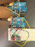
I'v now got my two-Arduino version of a multiiple ToF sensor LiDAR working.
I have only tested it with two sensors; I'll add one more later, and report, but the code should work with more.
I'm a little hesitant about that claim. The Slave Arduino code has little spare memory but I've tried to reduce requirements to a minimum. I have more VL53L0X sensors on order, and I am hoping I can handle up to eight.
That would allow a robot to get a good sense of the closest obstacles.
The Slave code uses an SPI interrupt routine modified from Nick Gammon's excellent example.
The code that configures and then reads from the ToF sensors is a complete rewrite of Adafruit's example code for dual VL53L0X sensors.
I'm no expert at C programming, so if you can see improvements (or bugs), let me know!
The code is on GitHub, along with some minimal documentation.
The next step will be go get the Arduino slave working with a micro:bit master; then I'll need to work out how to install hardware and software on Anastasia to help her avoid collisions.
Here's the core code for the slave:
const byte MAX_OK = 253; // largest acceptable range / 2
const byte NO_SUCH_SENSOR = 255;
const byte INVALID_READING = 254;
const int SENSORS = 2; // two sensors for now
// addresses we will assign to sensors
byte address[SENSORS];
// pins to shutdown
byte shutdown_pin[SENSORS];
// scaled distances
byte distance[SENSORS];

// create array of sensors
Adafruit_VL53L0X lox[SENSORS];
VL53L0X_RangingMeasurementData_t measure;

void setID() {

  int i;
  for (i=0; i < SENSORS; i++) {
    shutdown_pin[i] = i + 2; // pins go from 2 to SENSORS + 2
    address[i] = (byte) 0x30 + i;
    // addresses go from 0x30 to 0x37
    pinMode(shutdown_pin[i], OUTPUT);
    digitalWrite(shutdown_pin[i], LOW);
  }
  delay(10);
  for (i=0; i < SENSORS; i++) {
    digitalWrite(shutdown_pin[i], HIGH);
    delay(10);
    bool result = lox[i].begin(address[i]);
    if(!result) {
      while(1);  // loop forever if the setup didn't work
    }
  }
  delay(10);
}

void readSensors() {
  for (int i=0; i < SENSORS; i++) {
    float range;
    lox[1].rangingTest(&measure, false);
    if (measure.RangeStatus != 4) {
      range = measure.RangeMilliMeter;
      distance[i] = min(range / 2, MAX_OK);
    } else {
      distance[i] = INVALID_READING;
    }

  }
}

void setup() {
  // turn on SPI in slave mode
  SPCR |= bit (SPE);

  // have to send on master in, *slave out*
  pinMode(MISO, OUTPUT);
  setID();
  SPI.attachInterrupt();
}

// SPI interrupt routine
ISR (SPI_STC_vect)
{
  byte c = SPDR;  // grab byte from SPI Data Register
  // return scaled distance or error code
  SPDR = c < SENSORS ? distance[c] : NO_SUCH_SENSOR;
}  // end of interrupt routine SPI_STC_vect


void loop() {
  readSensors();
  delay(100); // read all sensors every 1/10 second
}


Comments
Post a Comment