3 Simple steps to test your new Arduino Clone:
is your brainchild going to work?
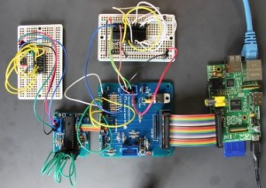
You've built your latest (or maybe your first) Arduino clone. It might be breadboarded, on stripboard, or a PCB. You've visually checked the connections, over and over, and maybe done some quick continuity checks with a multimeter. Everything looks fine. But will it actually work?Follow these steps to check it out.
Use blink- The Secret Sauce
Here's my secret sauce for building testable clones:- Use a chip that has both a bootloader and the standard blink sketch pre-loaded.
- Use a 5V LED for testing.
Use a chip that has both a bootloader and the standard blink sketch pre-loaded
When you test your clone with a pre-prepared chip, you're starting with a known good core component. If the blighter doesn't blink you know you've made a mistake in the wiring. For more detail on why this is a goo idea on courses, see here.A 5v LED is the tester's friend
Many makers have yet to discover the wonders of the 5V LED. In case these components are new to you, I'll explain what they are and why they work so well in this situation.Normally you need to use LEDs in series with an appropriate load resistor. This limits the current through the LED. If you omit the load resistor, the LED will rapidly burn out.
With 5V LEDs, you don't need an external load resistor because the LED maker has built one into the LED.
You can connect the LED across 5V directly and it will light up, confirming that there's 5V between the (negative) cathode and the (positive) anode. You can tell which is which because the anode is the longer lead, just like a normal LED.
Plug one into your circuit across your power supply rails, and you have an instant power-on indicator.
Connect the anode to +5V and the cathode to pin 13 (which is adjacent) and the blink sketch will flash your LED on or off.
Place one across ground and TXD or RXD and you can see if serial data is being transmitted.
Share this: A 5v LED is the tester's friend.
I love 5V LEDs and use them a lot.
If you're in the UK you can get the ones I use from Farnell. Farnell also stock 3.3V LEDs which are useful if you're working with a Raspberry Pi, an mbed or a teesny 3.x.
If the LED doesn't come on when you connect things, disconnect quickly and move on to troubleshooting.
Next, load a sketch
I'm going to make a couple of assumptions here: your Arduino clone has some way of uploading a sketch, and it involves an FTDI cable or equivalent. Since 95% of the clones I've seen satisfy this criterion, it's pretty likely that this applies to you.In that case, the next step is simple. Connect your clone to your computer, and try to upload a sketch.
There are a couple of things to watch out for here; you'll need to make sure that the Arduino IDE has the right board and the right port selected.
I develop on Linux, and the FTDI cable normally shows up as /dev/ttyACM0. If you're not sure how to find out which port to use, the Arduino website has good advice for Windows, Linux and OS/X users.
You'll also need to tell the Arduino IDE what board you're programming.
If you're using an Atmel ATMega328p (which I recommend) with a 16 MHz crystal (which I also recommend), chose Arduino Duemilanove w/ Atmega328
Which sketch should you use?
The simplest sketch to use is the Basics/Blink example. Open it from the Arduino IDE and click the upload Icon. The IDE will show you when it's compiled and will then upload it.You're looking for a message 'done uploading' on the status bar. If you see that, the upload worked; go on the next step. If not, go to troubleshooting.
Now tweak it and marvel at your success
If you are as skeptical as a good engineer should be, you'll want to do one more test: change the blink sketch and watch your clone's behaviour change.Edit the sketch by changing the delays in the LED blinking loop from 1000 to 100. After the change, the relevant bit of the sketch should look something like this:
// the loop routine runs over and over again forever:

void loop() {
  digitalWrite(led, HIGH);   // turn the LED on (HIGH is the voltage level)
  delay(100);               // don't wait for a second :)
  digitalWrite(led, LOW);    // turn the LED off by making the voltage LOW
  delay(100);               // wait for a tenth of a second
}
When you have uploaded the changed sketch you should see the LED blinking much faster. If so, you're done. You have a working clone. Time for a break and a celebration!


Comments
Post a Comment