Bus Pirate to the rescue
Yesterday was frustrating but instructive. I started testing the radio link to TrackBot. At a minimum I want to create a dead man's handle to prevent the robot from careering into a wall. Some control over direction and speed would also be useful.
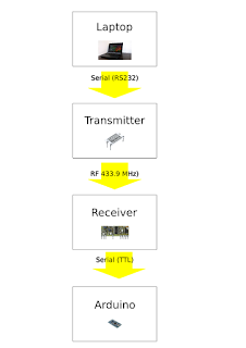 I'd set up an arrangement like this a few year back using a LEGO base and an AVR conrtoller. I kept the hardware but I was a bit lazy about project notes in those days. However, I knew that I'd been able to transmit commands from a Laptop to the AVR and I still have the receiver, the trnasmitter, and the hand-wired RSR232 cable and connector that I used to send sigmals from the Laptop.
I spent hours trying to get the arrangement working with Trackbot. I could detect when a character was being transmitted, but it wasn't being sent correctly. Usually this is a baud rate, frame length or parity issue, but not this time.
I checked and rechecked code and comms settings, but to no avail.
Time to try the Bus Pirate.
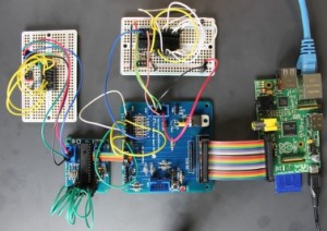
The Bus Pirate is an open-source troubleshooting tool which you can use to snoop or send messages in various protocols - I2C, SPI and Serial comms among others. I got mine from Proto-Pic along with its cables.

I linked it up to my receiver and confirmed thad data was not being received as expected. Each character was reported as having a framing error. I checked the transmitter where I saw the same problem.
Eventually I gave up, packed up for the evening, and had supper. Later that evening I had a flash of inspiration. What if the signal was inverted?
The Bus Pirate has an option to invert a serial comms signal; as soon as I turned it on, the framing errors disappeared and the Bus Pirate correctly reported the characters I was sending. A quick Google search, and I remembered what I had found out years ago: RS32 comms is active-low, but TTL comms is active-high. In other words, a 0-bit going down an RS232 cable is represented by +12v, and a 1-bit by -12V. TTL is not inverted; a TTL 0-bit is 0v but a 1-bit is +5V. Since one end of the link uses RS232 and the other uses TTL, every character gets garbled.
Last time round I fixed this by software. This time round I can simplify the transmitter circuitry and use an FTDI USB to TTL comms cable for the transmitter. But not today - I am waiting for a replacement soldering iron stand. So it's time to do some more I2C development on the BeagleBoard.

I spent hours trying to get the arrangement working with Trackbot. I could detect when a character was being transmitted, but it wasn't being sent correctly. Usually this is a baud rate, frame length or parity issue, but not this time.
I checked and rechecked code and comms settings, but to no avail.
Time to try the Bus Pirate.
The Bus Pirate is an open-source troubleshooting tool which you can use to snoop or send messages in various protocols - I2C, SPI and Serial comms among others. I got mine from Proto-Pic along with its cables.

I linked it up to my receiver and confirmed thad data was not being received as expected. Each character was reported as having a framing error. I checked the transmitter where I saw the same problem.
Eventually I gave up, packed up for the evening, and had supper. Later that evening I had a flash of inspiration. What if the signal was inverted?
The Bus Pirate has an option to invert a serial comms signal; as soon as I turned it on, the framing errors disappeared and the Bus Pirate correctly reported the characters I was sending. A quick Google search, and I remembered what I had found out years ago: RS32 comms is active-low, but TTL comms is active-high. In other words, a 0-bit going down an RS232 cable is represented by +12v, and a 1-bit by -12V. TTL is not inverted; a TTL 0-bit is 0v but a 1-bit is +5V. Since one end of the link uses RS232 and the other uses TTL, every character gets garbled.
Last time round I fixed this by software. This time round I can simplify the transmitter circuitry and use an FTDI USB to TTL comms cable for the transmitter. But not today - I am waiting for a replacement soldering iron stand. So it's time to do some more I2C development on the BeagleBoard.


Comments
Post a Comment