Posts

Showing posts from 2010

The mbed is here, along with his brother...

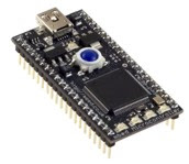
Yesterday my mbed arrived from Farnell/Element14, ready for me to road-test. It was accompanied by an LPCXpresso board which I'd ordered from Farnell at 6pm the evening before. Amazing! I'm posting my first impressions of the mbed on the element14 website, but it's worth posting a quick comparison of the two products here. Getting started with the mbed   The mbed really is as easy to get going as the website suggests; the cloud-based compiler means that there is no software setup for you do do. Fantastic! Here's all you have to do to get started: Connect your mbed to your PC using the supplied micro USB connector. This opens a USB storage device. Click on MBED.HTML and register. Download the HelloWorld.bin program. Copy to the mbed's file folder. Press reset on the mbed and watch its LED blink. Job done! This took less than 60 seconds; another 60 and I'd compiled my own variant of hello world, downloaded and ran it. There are lots of easy-to-use

Three cheers for Element14 and the mbed!

Image
I heard a couple of days ago that Element14 are sending me an mbed to road-test. Element14 is the online electronic design community sponsored by Premier Farnell . They organised the excellent Eagle course that I attended a few weeks ago. They also run a road-test programme where manufacturers donate interesting hardware for lucky designers to try out and review. I declared my interest in trying the mbed a few weeks ago, but so did the rest of the world; just about anyone who's involved with embedded systems would want to try out this neat product. The mbed is an ARM-based component for rapid prototyping of microcontroller applications. It's fully featured but very compact. It comes with extensive libraries, and its free development tool chain is online. Setting up and maintaining a development tool chain tends to be expensive or fiddly, so zero setup and zero cost are a big plus. I'm hoping that the mbed will arrive tomorrow. When it does I'll be reportin

Veroduino Mk 2

Image
I'm making good progress on my MicroWriter clone. I decided to start by building Mk 2 of my Veroduino . Mk 2 is more compact, and the green LED is connected to pin 13 by a jumper; one of my keyboard circuits needed to use pin 13 as an input, and the LED would have interfered with proper operation. Mk 2 uses as resonator rather than a crystal; it also corrects a defect in the Mk 1 design, which tied the analog reference voltage pin ( Aref ) to Vcc . Aref is not normally connected; if it is, it should linked to ground by a small capacitor, but that's only recommended if you are doing very precise analog measurements. I've corrected the schematic .

Microwriter revisited

Image
I'm taking a break from Test Equipment, and resuming a project that has been on hold for a couple of years. It's a home brewed compact one-hand chorded keyboard inspired by the Microwriter . I started the project using an Atmel ATMega8 hosted on SimmStick hardware. My tools for software development were primitive. WinAVR was still in its infancy, so like most Atmel developers I used AVR Studio and programmed in assembler or programmed in BASIC using Bascom from MCS Electronics. I decided to use I2C to connect the micro controller to the keypad and LCD display. Driving I2C in assembler was a pain, and writing the keyboard handling in Basic was positively soul-destroying. I decided to wait until technology had improved enough to make the project enjoyable. Fast forward two years. The Arduino offers an affordable hardware platform and an easy-to-use IDE. The main challenge is the keyboard itself; I'm going to experiment with QTC pills which look perfect for this sort

Arduino I2C Data Logging Board

Image
I'm making great progress with my family of I2C™-based Test Equipment. This data logger is one of the smallest, cheapest and simplest boards so far. It uses a 247C256 eeprom memory which has an I2C interface. This gives 32k bytes of external memory. The chip is widely available for £1 or so. This picture includes a five-pence piece to give some impression of the scale. If you're logging something like sunlight or wind speed, 32k bytes allows you to log an 8-bit value every minute for over 22 days. A small design change would add more memory; the chip has eight possible addresses, so a board can contain eight of these chips, storing a total of 256k bytes. Other chips offer even greater memory capacity. The back of the strip board has just 3 breaks, with pins 1-4 of the chip strapped to ground. That sets the configurable part of the chip's I2C address to 0. You can drive the board with the Arduino's Wire library, and there is a sketch using this chip in the

Arduino as an ISP

Image
Yesterday, while experimenting with my Veroduino board, I managed to destroy its boot loader. Annoying, but not a show-stopper; I'd recently built the USBTinyISP from Adafruit, and felt sure I could quickly restore the corrupt boot loader. Revenge of Windows 7 Not that simple, alas. I attached my USBTiny to my Windows laptop. It runs Windows 7, which refuses to load unsigned drivers without some fairly vigorous persuasion. Even when persuaded, it would not load the driver for the USBTiny. I think the driver may not not compatible with my laptop's 64-bit AMD processor. After an hour of  unsuccessful experimentation I decided to try something else. My next two attempts also failed. I can drive the USBTiny using avrdude on one of my Linux servers, but I can't install the latest Arduino IDE on that machine. The server is is running Ubuntu Hardy Heron, and I can't upgrade it easily. Its main job is to act as VMware host to a bevy of virtual servers, and VMware server

Arduino DVM with LCD Display

Image
A Digital Voltmeter (DVM) is one of the first things you need if you're building electronics projects. Most of us have one. But what if you need more than one? Enter the Arduino. If you have an Arduino that can drive an LCD, you've got a multi-channel voltmeter! #include <lcdi2c.h> #include <wire.h> int ADDR = 0x21; LCDI2C lcd = LCDI2C(ADDR); float volts[4] = {0.0}; int pin; void setup() { Wire.begin(); lcd.init(); lcd.print("4-ch Arduino DVM"); } void loop() { lcd.cursorTo(2,0); for (pin = 0; pin < 4; pin++) { volts[pin] = (5.0 * analogRead(pin)) / 1023; lcd.print(volts[pin], 1); lcd.print(" "); delay(10); } } The sketch above turns an Arduino with an I2C LCD display into a four-channel voltmeter. The Atmel ATMega328 on which the Arduino is based has six analog inputs but two of them are used by the chip's I2C support. That leaves four channels - plenty for most purposes. The sketch uses my LCD I2C library; I

An Excellent Eagle Course

Image
I spent this Saturday at a free CadSoft Eagle course for Arduino users which had been organised by Tinker London and Farnell's Element14 . Over twenty of us crammed into a well-equipped course room at the Cavendish Conference Centre. The main presenter was Tinker's Peter Knight. Alexandra Deschamps - Sonsino (the CEO and co-founder of Tinker) explained that when she first asked Peter to run the course he said he could cover the subject in three weeks. Somehow he managed to cover the essentials in just a few hours! Peter was supported by Lynn Ma, Mei Wang and Alistair Winning from Farnell , and by Richard Hammerl from CadSoft . Richard knows Eagle inside-out; he's an active member of the Eagle forum on Element14, so I know I'll get a fast and helpful response to any queries I have about using the software. Everyone had done their homework and arrived with the latest version of Eagle on their laptops. In the morning Peter covered creating a schematic and layi

I2C LCD board

Image
In the previous post I mentioned that most of the boards I'm working on use I2C™ port expanders. The latest is an LCD driver which uses a Phillips PCF8574 I2C 8-bit expander to drive a 2x16 character LCD. The only Arduino pins used by the display are pins 27/28; they can be used to drive other I2C boards as well. The Arduino software to drive the LCD is very simple. Here's the code used for the picture above: #include &lt:lcdi2c.h> #include <wire.h> int ADDR = 0x21; LCDI2C lcd = LCDI2C(ADDR); void setup() { Wire.begin(); lcd.init(); lcd.print("test"); } void loop() { lcd.cursorTo(2,0); lcd.print("time:"); lcd.cursorTo(2,6); // print the number of seconds since reset: lcd.print(millis()/1000); }

Simple LED Bar Logic Tester

Image
What happens when you power-up your latest electronic creation for the first time? Sometimes it just works, but for most of us that's the exception rather than the rule. If your circuit isn't working as expected, how do you track down the problem? I've been using this LED Bar Logic tester to debug some of my Arduino™ add-ons. It's very simple - a row of sockets connects to a ULN2803A, which drives 8 of the LEDs in a 10-LED bar display. The ninth LED is unused; I use the tenth to indicate if the 5v supply is on. Most of the boards I'm working on at the moment are driven by an I2C™ port expander. I use the LED bar tester to check that the state of the port expander outputs is what I expect. Of course you can also use it to check the status of  the Arduino pins. Here's the schematic. SCL and SDA are usused; they are part of the I2C bus which runs along the bottom of all my test boards.

Fritzing is fun!

Image
An Electronic CAD program I can live with and it's free! Readers will know that I'm sceptical about Electronics CAD software. Most of what I've tried seems counter-intuitive, and the open source pacakges have either been buggy or hard to install. A couple of days ago I discovered Fritzing , and I'm really enthusiastic. Fritzing is alpha software, but it's very usable - indeed, Adafruit (one of the best-known names in the Open Source Hardware space) have been using it for months. Here are the features I like the most: You start by creating a virtual breadboard of your project. Here's a sample of the breadboard view for an Arduino-based hardware 'Hello World' ( a flashing led circuit). You create it by dragging components from a bin and placing them on your work surface. When you drop a component on the breadboard it's automatically plugged in. You can select wires and drag them to the things they connect to. I find the interface is v

Arduino on a budget - part 7

Image
My Veroduino is compact, cheap and easy to use. The Mk 1 is a little fiddly to construct; I hope to build Mk 2 as soon as the components arrive. The two strips alongside the microprocessor (MPU) allow you to link plugboard components to any MPU pin. The male jumper to the left of the MPU allows you to provide power from a FTDI USB TTL cable , and to program the device using the Arduino development environment. The pushbutton resets the MPU; you need do a manual reset while programming. Timing the reset is a matter of trial and error. I will buy and build a USB breakout board soon. That should perform an auto-reset when programming. The boad is built on a type of Vero stripboard which has a central break in all the coper trackes. This is ideal for boards which carry Dual-in-line chips like the MPU. The board layout is very simple, with only five manual strip breaks needed. Four of the breaks are underneath the jumper for the FTDI cable. The outside jumper pins are soldered to stipboard

Developer shot by Arduino™!

Image
Here is the first photo taken by my latest acquisition, a low-cost CCD colour camera and Arduino-compatible trigger/capture board. I bought them both from S K Pang - a UK supplier who provided very quick delivery. They appear identical to the camera and trigger described on the SparkFun website. Sadly, supplies of both components are likely to be limited. The manufacturer has replaced the camera with a higher-function model at a much higher price. The trigger is no longer offered on the S K Pang website and Sparkfun shows the camera as out-of-stock. This is frustrating, as the combo are fairly inexpensive and easy to use. Picture quality is not what you'd get from a digital camera but it's good enough for robotics vision projects and for the boat security application that I'm currently working on. The camera has a well-documented UART interface. When fired, the trigger board requests a jpeg image from the camera and records it on a microSD memory card. The trigger board i

Arduino on a budget - 6

Image
Here is the corrected schematic for the Veroduino Mk 1. I'll describe it in a bit more detail tomorrow, and post a better photo.

Why are CAD tools so hard to use?

Years ago, when IBM was introducing thousands of its employees to the brave new world of object-oriented software, I found myself co-teaching an OO Analysis and Design course to a group of IBMers . My co-instructor and I were both independent contractors, but we were supported by an old friend who worked for IBM. After a particularly frustrating practical one of the students asked "Why are we using Rational Rose to draw our designs? It sucks." The IBMer replied: "All modelling tools suck. It's just that Rose sucks less." I've just had a similar experience trying to get started with Schematic Editors. I wanted to draw a schematic for the Veroduino - the low-cost, compact Arduino clone that I built a few days ago. I'd read that TinyCAD was very intuitive. I got going fairly quickly, but could not find a library with all the parts that I wanted. I tried to add a new library of my own; that process turned out to be so intuitive (not) that it crashed

Arduino on a budget - part 5

Image
Introducing the Veroduino The Veroduino is inspired by the Paperduino , Adafruit's Boarduino and Oomlout's Breadboard Arduino Compatible Kit . I built it on a length of Vero's 01-0171 stripboard . It's a narrow board with a central gap in the conductive strips. It's perfect for DIL components. I used Oomlout's Arduino Compatible Component Bundle and a set of stackable headers . The Veroduino Mk 1 has room for a 5v regulated power supply but for now I am using the FTDI USB TTL serial cable from Oomlout to program the board and to provide power. Veroduino Mk 1 almost fits on the stripboard but the Crystal overhangs the edge by about a millimeter. Mk2 will use a ceramic resonator and should be both cheaper and smaller. The cost of the Veroduino is under £15 inc VAT. You will also need a serial cable (£15.50 inc VAT). Oneof these can be used to program as many Veroduino boards as you want. You can develop and download software to the Veroduino using the Arduino d

Back in business

It took a couple of days to sort out the hardware problems that hit me last week. It seems that the CPU in my workstation has fried itself. I think I know why, and I'm hoping that a new CPU will fix the problem. At one point it looked as if two servers had also failed, but it turned out to be a problem with my aged UPS. I had to do a bit of re-cabling but both servers are ok. I removed the hard drive from the workstation and mounted it in one of the servers. All the data was there, which was a relief. The drive was reasonably well backed up but I would have lost a day's work - annoying rather than catastrophic. As it is I've lost nothing. I am using my Toshiba laptop as a temporary replacement. Its major disadvantages are that it's a Windows 7 machine and has no parallel port. I got back to Arduino development on Thursday; on Friday the USB to TTL cable arrived from Oomlout, and I now have my Veroduino working. I'll write about that soon. Meanwhile, I'd like to

Arduino on a budget - part 4

Normal service will be resumed as soon as possible! Yesterday my worksation died, and one of my servers failed. I'm currently a bit preoccupied, trying to find the root causes of the failures and restoring data busily. I hope to be able to get back to some Arduino work later today.

Arduino on a budget - part 3

Image
The best-made plans... I'd hoped to build version two of Veroduino (my Arduino clone on a strip-board), using a narrower piece of strip-board than my first attempt. Alas, the new version was too narrow; if you use a crystal for the controller's oscillator you need to connect it to a couple of capacitors, and I couldn't find a workable layout in the limited space available. I decided to use a SimmStick . SimmSticks have fallen out of fashion as the USB has taken over, but they still work well and I had a suitable board from Dontronics . The SimmStick can take a 28 or 40-pin Atmel AVR micro-controller; it took an hour or so to polulate the board and check it out. I already had a motherboard which provides power and RS232 comms if required. I modified the motherboard by adding a 30-pin PCB header. That gave me access to all the lines of the SimmBus; these include the SDA and SCL signals needed for I2C, as well as Ground and the 5v supply needed by my I2C boards. I now have a

Arduino on a budget - part 2

Image
I've made good progress with Veroduino - the Arduino clone I'm building on Veroboard™*. I like to build up complex circuits from pluggable components. They are easier to test, easier to replace, and can often be used in more than one project. I started by building a pluggable power supply on a small piece of strip-board; it contains a 5v regulator, and includes a bridge rectifier to provide polarity protection. Next I started on the board that carries the micro-controller. I abandoned my first prototype; the strip-board turned out to be too wide, covering the breadboard pads that connect to the pins of the micro-controller. I didn't feel too bad about that; the reason that I prototype is to discover design flaws early. I also verified that my mechanical design plugged into the board correctly. It's tempting to use PCB header pins, but they don't play well with this design. They work really well with a two-sided PCB, because the header can be soldered from the top.

Arduino on a budget - part 1

Image
Readers will know that I'm a fan of the Arduino, as is my daughter Alex . We currently share an Arduino board. I'm in the middle of a lengthy project, and I don't want to delay her access to the board. The obvious solution is to get a second Arduino. An Arduino Duemilanove board costs about £25 in the UK , and I'd prefer not to spend that much. Luckily the Arduino is open source, so lots of companies have developed their own versions. One popular alternative is the Boarduino from Adafruit , shown above. It's an Arduino clone with a much smaller footprint. You can't use standard Arduino Shields, but you can plug it into a breadboard - hence the name. If you're based in the UK .:Oomlout:. currently offer the Boarduino for £13.50 . I'd willingly spend that much, but a quick web search turned up two even cheaper possibilities; the Paperduino and the Stripboard Arduino . The Paperduino is a cool idea, but I'm looking for something a bit more robust, a

Introduction to Electronics for Hobbyists

Image
I just came across an excellent intro to Electronics. It's a great starting point for beginners in Electronics and a useful reference for veterans. The sections give a good overview of commonly used components. The page on resistors includes a very nice guide to colour codes. There are several pages on construction , including a soldering guide . It's generally good, though the reference to lead-based solder is a little outdated. The kits are commercially available from RSH Electronics . If the kits are as good as the website, they are worth a look! (Image from Wikimedia creative commons)

Basics of I2C™

Image
The I2C bus allows you to connect several peripherals to one or more master controllers. In this diagram the controller is an Arduino; it is connected to a port extender and an LCD display. One commonly used port extender can drive up to 8 i/o lines; you might use four lines to control LEDs, and four lines to read push-buttons. It's a simple IC chip which costs about £1. All you do is connect it to ground, to a 5 volt power source and to the two data lines that form the I2C bus. The Arduino has a Wire library which allows you to turn the output lines on or off, and to read the state of the input lines. A commercial I2C LCD display is a bit more expensive (about £30). I built my own using a cheap serial LCD module (about £7) wired up to a port extender. I drive it using a modified Arduino library which someone else wrote for a slightly different port extender chip. The Arduino supports the original version of the I2C protocol which allows me to connect up to 127 different devices t

Arduino rocks!

Image
I've fallen in love with the Arduino . This amazing piece of hardware brings micro controllers to the masses. It was designed for non-geeks who want to do physical computing, but it's turned out to be just as popular with geeks. The Arduino provides a fun, inexpensive, easy-to-use platform for electonics and robotics. Best of all, it's open source - part of a radical extension of the open-source concept from the software world to the world of hardware. I'm currently working on a family of low-cost electronic test equipment, driven by an arduino and connected by an I2C™ bus. I'll be using an attached PC for graphical display. I'll blog about progress here. I will open-source and publish the hardware and software designs, and may even offer parts kits if there's enough interest. (Image from Wikipedia - placed in the public domain by its author).