Build a Web-based DVM using Arduino and Pi zero W

If you’re experienced and impatient you will find software and basic installation instructions on GitHub.
If you’re less experienced, don’t worry. All you need to know is:
- how to compile and download an Arduino sketch,
- how to connect your Raspberry Pi to your network, and
- how to open a terminal session on the Pi.
The WebDVM uses some general techniques that you can apply to projects of your own
In Part 1 (this post) you will install some simple Arduino code, connect the Arduino to a Pi, and check that the two are communicating.
In Part 2 you’ll use a short Python program on the Pi to read the Arduino’s output.
In Part 3 you'll use a simple technique to turn your Python program into a web server, and you'll use HTML and JavaScript to format the output. You’ll see the web page displaying the voltage the Arduino’s six Analog inputs in real-time.
Why Pi and Arduino?
The project plays to the strengths of both platforms.
The Arduino has 6 analog inputs.
The Pi zero runs Python, it can connect using WiFi without extra hardware, and it’s inexpensive.
Both are widely available.
What hardware do you need?
Here’s what I used:
- An Arduino Uno.
- A Raspberry Pi zero W with wifi set up.
- A battery to power the hardware.
- Cables to connect the Pi and Arduino, and to provide power to the Pi.
- Something that runs a web browser on the same network as the Pi.
I used an Arduino Uno but an older model or a Leonardo would be fine. If you have a nano or mini you will need a way of connecting what you want to measure using a breadboard and/or headers.
You can use a full sized Raspberry Pi if you want. Any model will work, and you can use a wired (Ethernet) connection instead of wifi.
Arduino software
The Arduino sketch is really simple. It
- sets up serial communication,
- reads each analog input, and
- prints the voltage to serial output.
Here’s the sketch:
const float vcc = 5.0;
const float scale = vcc / 1023;
const int analogPins[] = {A0, A1, A2, A3, A4, A5};
const int delay_ms = 50;
const int channels = 6;
// 6 Channel DVM over serial connection
void setup() {
//Initialize serial and wait for port to open:
Serial.begin(9600);
while (!Serial) {
}
}
void loop() {
// read each Analog channel, scale it,
// and print a formatted version to the Serial output
for (int i = 0;ifloat v = scale * analogRead(analogPins[i]);
Serial.print('A');
Serial.print(i);
Serial.print('=');
Serial.println(v);
delay(delay_ms);
}
}
Compile and upload the sketch to the Arduino.
If you open the serial monitor, you should see a window like this:

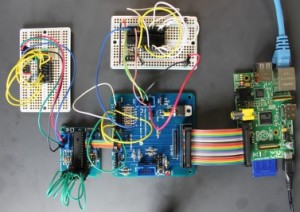
Now connect the Pi to the Arduino.
If you use an Arduino Uno or Leonardo, you’ll need a USB cable with an A-type connector at one end; it will probably have a B-type connector at the other. If you want to connect that to a Pi zero, you’ll need an adapater; if it’s a full sized Pi you wan connect directly.
Open a terminal window on the Pi.
If you type
ls la /dev/ttyACM0
you should see an entry for /dev/ttyACM0

/dev/ttyACM0 is a temporary teletype device that raspbian created when you connected the Arduino.
It’s owned by root, and is in the dialout group. As user pi you should already be a member of the dialout group, so you can access the device.
Type
cat -v /dev/ttyACM0
This lists the output that the Pi is reading from the Arduino, with non-printing characters displayed.

The ^M characters are newlines sent by the Arduino after each Analog reading.
Coming next
That concludes the first part of the project. In the next part you’ll read the Arduino’s output in a Python program on the Pi.
Don't forget to follow @rareblog on Twitter to see when the next part is posted!


Comments
Post a Comment