Arduino on a budget - part 7
 My Veroduino is compact, cheap and easy to use.
The Mk 1 is a little fiddly to construct; I hope to build Mk 2 as soon as the components arrive.
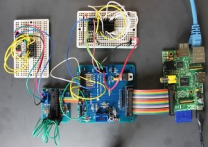
The two strips alongside the microprocessor (MPU) allow you to link plugboard components to any MPU pin.
The male jumper to the left of the MPU allows you to provide power from a FTDI USB TTL cable, and to program the device using the Arduino development environment.
The pushbutton resets the MPU; you need do a manual reset while programming. Timing the reset is a matter of trial and error. I will buy and build a USB breakout board soon. That should perform an auto-reset when programming.
 The boad is built on a type of Vero stripboard which has a central break in all the coper trackes. This is ideal for boards which carry Dual-in-line chips like the MPU. The board layout is very simple, with only five manual strip breaks needed.
Four of the breaks are underneath the jumper for the FTDI cable. The outside jumper pins are soldered to stipboard tracks; the rest of the used pins are soldered to three wires which come down from the top side of the board through three small holes.
One pin has been removed from the jumper, as that signal (CTS# on the FTDI cable) is not used.
The fifth break (on the bottom row of strips towards the right of the board) is there to support thegreen pin13 status LED. Both leds are 3v 3mm types with a built-in current limiting resistor from Maplin.
The board uses components from oomlout's Arduino Compatible Component Bundle. I got the board and spacers from Maplin. The spacers need M3 bolts to secure them to the board.
My design for the board borrows heavily from the work of others; for details see part 1. The schematic is in part 6.


Comments
Post a Comment